


The deformation results from the reference 3D model (a) and the SHELL281 shell model (b) are shown in this figure:
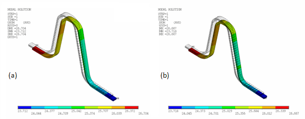
The maximum displacement for the shell model (26.667) nearly matches the reference value (26.704), with an error of only 0.14 percent.
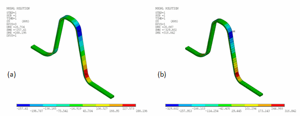
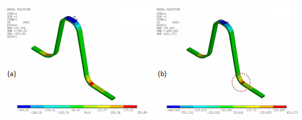
As expected, the highest stresses caused by the thermal load appear in the reinforcing ring, which has the largest curvature and curvature variation. Distributions of all three normal stress components (X - radial, Y - hoop, and Z - axial) agree closely with the reference results, as shown in the following three figures, where (a) refers to the reference 3D model and (b) refers to the shell model:
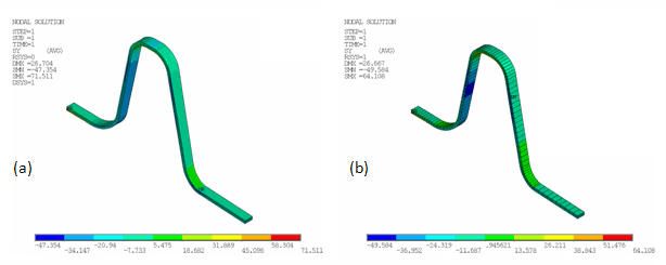
The following figures compare the detailed stress distributions from the reference model and the shell model, at both the bottom and top of the reinforcing ring:
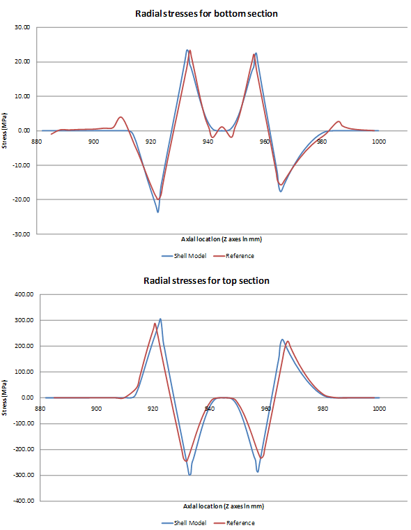
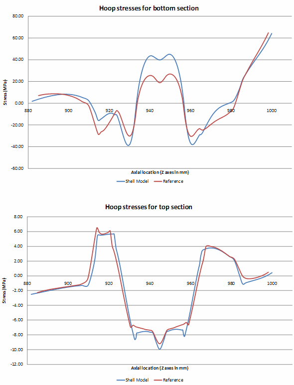
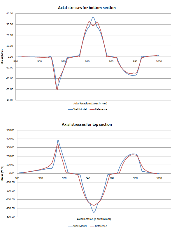
The generally accurate agreement between the reference and simulation stress results is clearly observable.
Some small local differences exist in the stress results, particularly at the areas where the ring connects with the main extension wall. The discrepancy is noticeable because the problem applies the SHELL281 element (which is based on the plane stress assumption) to a complex 3D domain.
If the problem were to be simulated with standard shell elements, no residual stresses would be obtained.
The stress contour display on the SHELL281 model with the expanded solid shapes reveals one graphics irregularity: result averaging may fail where the pseudo expanded interelement connectivity does not match, as shown in the circled area of (b) in Figure 11.10: Nozzle Axial (Z) Stress. To overcome this issue, use the (default) simple area element display option (/ESHAPE,0).