


To apply the boundary conditions, MPC-based rigid constraints are defined at both ends of the tube and the coil. A pilot node is defined at each end and is attached to CONTA175 elements generated at the end surface of the tube and the end nodes of the coils.
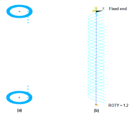
The pilot node at one end is fixed in all directions; the pilot node at the other end is rotated about the Y axis by 1.2 radians.