


Fixed-support conditions are applied near the hub portion of the cyclic-sector impeller blade model, as shown in this figure:
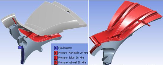
The following loads are considered for the cyclic-symmetry analyses:
Fluid pressure applied on the impeller blade
Centrifugal loads caused by rotational velocity
Thermal loads caused by the difference in reference temperature and applied temperature and due to thermal coefficient of expansion
The applied load is cyclically symmetric in nature. It is also possible to apply non-cyclically symmetric loading with
different loading values on each of the cyclic sectors
(CYCOPT,LDSECT,SECTOR).
The rotational velocity (OMEGA,0,6000,0) is applied along the global Y axis. The impeller blade assembly is modeled with a thermal coefficient expansion of 1.2e-005 °C-1. The reference temperature is held at 22° C and a body temperature of 50° C is applied on all nodes of the model to generate the thermal load vector.
The thermal load vector generated from the base static solve can be ignored in the subsequent analysis (THEXPAND).
For the full-harmonic, perturbed full-harmonic, and perturbed mode-superposition harmonic analyses, the pressure load applied on the main blade, splitter, and hub wall is treated as a harmonically varying load.