68.7. Results and Discussion

The following three figures show the fluid pressure and the deformed geometry during the simulation at the first, middle, and last substeps:

Figure 68.5: Fluid-Penetration Pressure Distribution at the First Substep

Fluid-Penetration Pressure Distribution at the First Substep

Figure 68.6: Fluid-Penetration Pressure Distribution at a Middle Substep

Fluid-Penetration Pressure Distribution at a Middle Substep

Figure 68.7: Fluid-Penetration Pressure Distribution at the Last Substep

Fluid-Penetration Pressure Distribution at the Last Substep

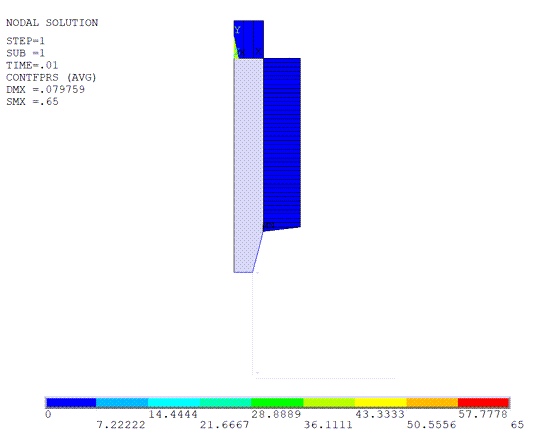
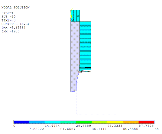
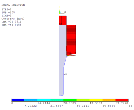
The plots show that when the contact element on the billet comes in contact with the die surface, the fluid pressure stops acting on it. The fluid pressure applied on the surface elements ranges from 0.65 MPa to 64.9 MPa at first and last substep. During the simulation, fluid does not penetrate the contact between the billet and the die surface, and the contact remains closed during the extrusion.

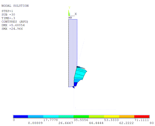
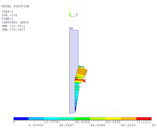
Successful prevention of fluid penetration is due to the fluid pressure never exceeding the contact pressure at any point in the loading history, as shown in the following three figures:

Figure 68.8: Contact Pressure Distribution at the First Substep

Contact Pressure Distribution at the First Substep

Figure 68.9: Contact Pressure Distribution at the 30th Substep

Contact Pressure Distribution at the 30th Substep

Figure 68.10: Contact Pressure Distribution at the Last Substep

Contact Pressure Distribution at the Last Substep

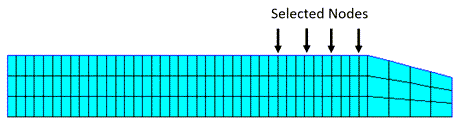
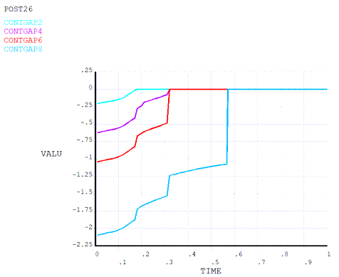
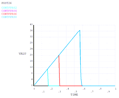
To confirm that the contact remains closed, the contact gap and contact fluid pressure on four selected nodes on the surface of billet are plotted against time. As the node comes into contact with the target, contact gap becomes zero and remains at zero, and the fluid pressure on that node is reduced to zero at the same moment:

Figure 68.11: Contact-Gap and Contact-Fluid Pressure Over Time on Four Selected Nodes

Contact-Gap and Contact-Fluid Pressure Over Time on Four Selected Nodes

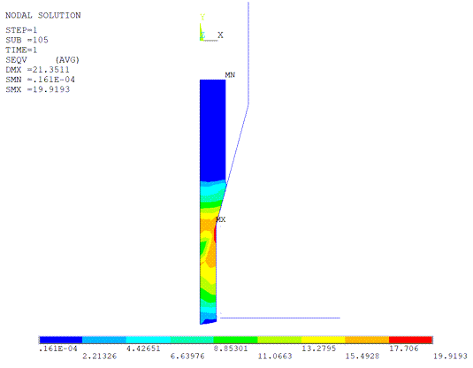
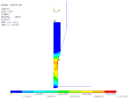
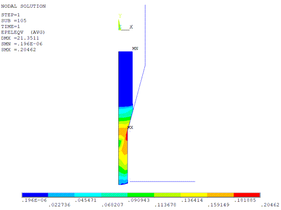
Because the billet exhibits large elastic and plastic deformation during the extrusion process, the von Mises stress, equivalent plastic strain, and equivalent elastic strain at the last substep are also captured:

Figure 68.12: Von Mises Stress at the Last Substep

Von Mises Stress at the Last Substep

Figure 68.13: Equivalent Plastic Strain at the Last Substep

Equivalent Plastic Strain at the Last Substep

Figure 68.14: Equivalent Elastic Strain at the Last Substep

Equivalent Elastic Strain at the Last Substep