


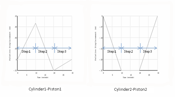
The entire digger-arm model is subjected to acceleration to account for gravity. The two piston-cylinder arrangements are also activated simultaneously. In the finite-element model, these piston-cylinder arrangements are represented as translational joints. Displacement boundary conditions are applied on the free relative degree of freedom of the translational joints. The displacements are applied over three load steps, as shown:
The following example input applies the acceleration and displacement loading (ACEL and DJ):
acel,%_acelx%,%_acely%,%_acelz%      ! apply acceleration loading via table
esel,s,type,, id1#                   ! select the first translational joint
dj,all,ux,%_load1%                   ! apply loads defined by table
esel,all
esel,s,type,, id2#                   ! select the other translational joint
dj,all,ux,%_load2%                   ! apply loads defined by table