This section discusses the results for both models used in this problem:
The following figures show the equivalent elastic strain and equivalent creep strain:
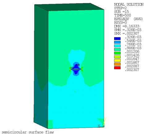
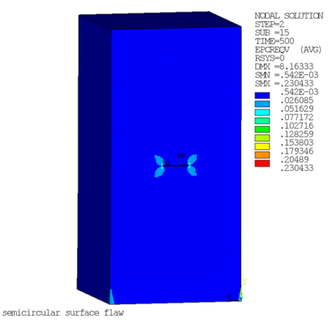
The creep strain is approximately 100 times larger than the elastic strain in the secondary creep stage, which dominates the entire specimen at the end of the simulation.
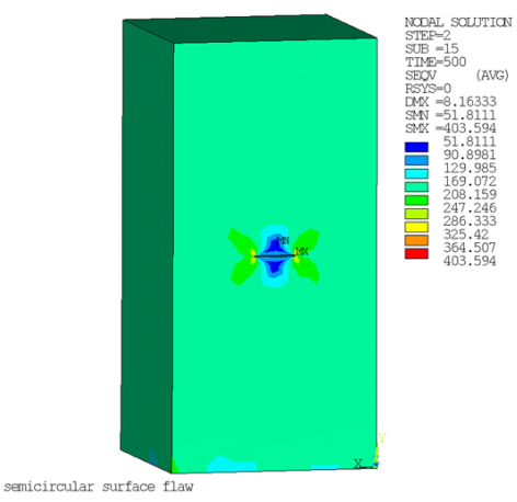
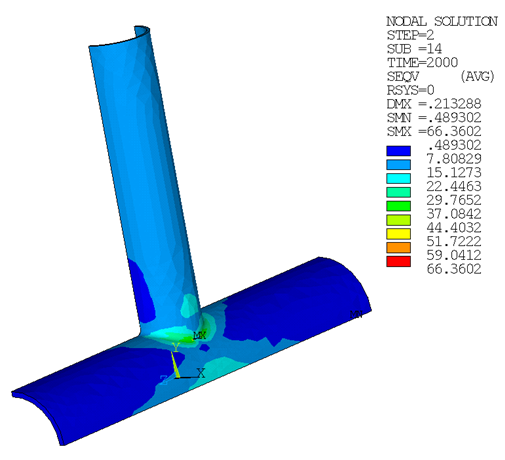
Following is the maximum Von Mises stress occurring at the crack tip:
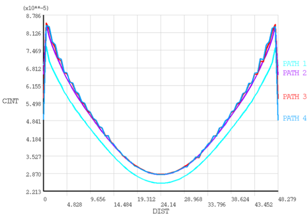
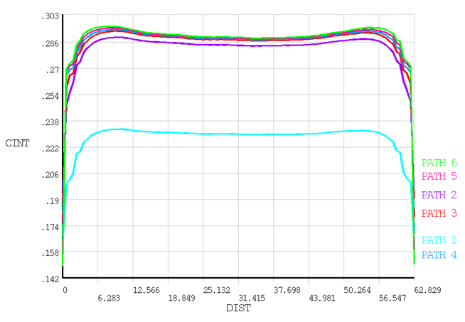
The following figure shows the C*-integral along the crack front for different contours, where the path-independence appears after path 3:
The following figures show the equivalent elastic strain, equivalent creep strain, and von Mises stress of the X-joint pipe with the warped flaw at the welded joint:
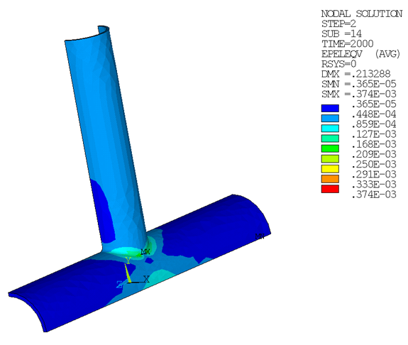
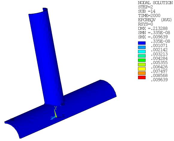
The creep strain is approximately 30 times larger than the elastic strain in the secondary creep stage, which dominates the local region of specimen at the end of the simulation.
The following shows the C*-integral values along the crack front, which gradually becomes path-independent after path 2.