


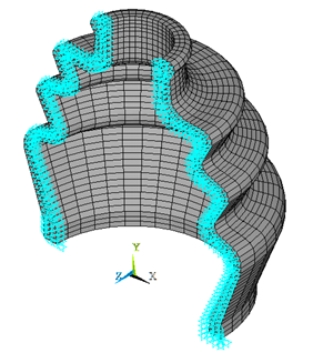
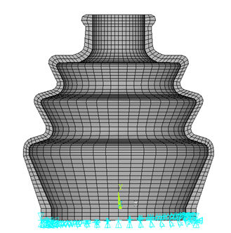
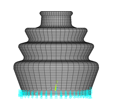
The model is constrained at the symmetry plane by restricting the out-of-plane translation as shown in Figure 26.5: Boundary Conditions at a Symmetry Plane. The bottom portion of the rubber boot is restricted in axial and radial directions as shown in Figure 26.6: Boundary Conditions at the Bottom of the Rubber Boot (in the Axial Direction) and Figure 26.7: Boundary Conditions at the Bottom of the Rubber Boot (in the Radial Direction).
The load is applied in terms of displacements and rotations through different load steps.
Load Step 1
Base node (pilot node) at the end of the shaft’s center axis is constrained in all direction as follows:
RIGID_BASE=1
RIGID_TOP =2
n,RIGID_BASE,0,0,0      ! Base node at the end of the
                        ! shaft’s center axis
n,RIGID_TOP,0,97,0      ! Top node at the shaft’s center axis
d,RIGID_BASE,all
Load Step 2
Boot seal gets compressed when the shaft moves down. The vertical movement of the shaft is governed by the displacement applied to the base node (pilot node) at the end of the shaft’s center axis. The following displacement is applied at the pilot node for the 2nd load step.
d,RIGID_BASE,uy,-10
Load Step 3
Shaft is rotated by giving certain amount of rotation about z-axis to the base node (pilot node) at the end of the shaft’s center axis, as follows:
d,RIGID_BASE,rotz,0.55