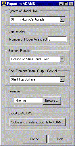
After building the model in Mechanical APDL (including all interface points), the next step is to invoke the Ansys-Adams Interface to create the modal neutral file, Jobname.mnf. Creation of this file is driven by a command macro called Adams.mac.
To start the interface, select the following GUI path.
The Select Interface Points dialog box appears first. From this dialog box, you must select two or more interface points.
Do not select too many interface points, as one point gives rise to six degrees of freedom in Adams. Too many interface points may lead to huge files and models.
After you confirm your selection, the Export to Adams dialog box appears.
Complete the following steps using this dialog box.
System of Model Units: The units used for the model is important to the Adams program, whereas Mechanical APDL only requires that you use a consistent set of units. The units chosen will be written to the .mnf file and can be recalled with the Adams/Flex module. If no units are specified, Adams assumes that the same units were used in Mechanical APDL as the ones chosen in the Adams model. See the /UNITS command for details. If you specify user defined units, a Define User Units dialog box will appear for you to input the conversion factors (for length, mass, force, and time) between SI units and your chosen units. Below is an example of user defined units in which the component has been modeled using millimeter, tonne (metric ton), newton, and second.
Length Factor = 1 meter/millimeter = 1000 Mass Factor = 1 kilogram/tonne = 0.001 Force Factor = 1 newton/newton = 1 Time Factor = 1 second/second = 1 Number of Modes to Extract: Input the number of normal modes to compute. Normal modes are the eigenmodes of the component with all degrees of freedom of all interface points fixed. The number of normal modes depends on the frequency range of the excitation you will apply in your Adams model. You must select a sufficient number of modes to represent your structure in that frequency range. In Adams, if you have chosen too many normal modes, you are able to deactivate eigenmodes based on the frequency or an energy criterion.
Element Results: Specify whether or not the program should write stress and/or strain results. This option has no effect on the output for beam elements. If you want to output stress and strain for only a subset of nodes, you should create a node component named "STRESS" before running the ADAMS command macro.
Shell Element Result Output Control: Specify the shell element output location (top, middle, bottom). This option has no effect on the output for solid elements and beam elements.
Filename: Specify a filename for the modal neutral file. The default name is Jobname.mnf. If a file with the chosen name exists, it will be moved to a file named filename.mnfbak.
Export to Adams: Select "Solve and create export file to Adams" to initiate the solution sequence. Static and normal modes are computed and all information required by Adams is written to the .mnf file specified above. Only the selected elements are considered. The current model is written to the database file Jobname.dbmnf.
Note: Note that the algorithm used to compute the .mnf file adds constraints to the interface points. If you create the .mnf file a second time using the same model in the same run, be sure to delete all constraints on the interface points (or resume the database file Jobname.dbmnf) before you run it again.
If you prefer to work in batch mode, you may choose to run the ADAMS command macro by command input. After building the model and defining interface points, use the following commands to compute the .mnf file.
/UNITS,Label        ! Specify the units chosen for modeling
NSEL,...            ! Select two or more interface points
SAVE                ! Save the model for a possible resume from
                    ! this point
Adams,NMODES,...    ! Activate Adams.MAC to compute the .MNF file
See the ADAMS command description for more information. When you use command input to compute the .MNF file, there is no option to change the file name. The default name of Jobname.MNF will be used.
It is a good practice to verify the correctness of the results after the .MNF file is created. Below are guidelines you can use to complete this task.
Check the number of orthonormalized eigenmodes in the Mechanical APDL output window. These eigenmodes are the result of an orthonormalization of the normal modes and the constraint modes. You should observe the following:
The number of modes equals the number of normal modes plus the number of constraint modes.
The first six modes are rigid-body modes. These are marked with "(probable rigid-body mode)." If there is a mode close to a rigid-body mode but not marked, you may deactivate it later in the Adams program.
If a mode is marked with "Infinity. Possible mass singularity. Ignored," check your model carefully. There might be a problem with the Interface points.
The first few modes are equal to the free-free eigenmodes of the component. You might want to verify this by doing a modal analysis: Set analysis option to ANTYPE,MODAL with MODOPT,LANB (Block Lanczos); activate the lumped mass approach with LUMPM,ON.
Review the normal modes (load step 1) and the constraint modes (load step 2) in the General Postprocessor.
Verify the transfer by doing a modal analysis of the component in Adams with all interface degrees of freedom fixed. Compare the results with the normal modes calculated in Mechanical APDL (load step 1).


