


These example problems highlight the benefits of nonlinear mesh adaptivity:
Consider a rubber seal simulation, with an initial geometry and mesh as shown:
Downward displacement is applied to the rigid surface on the top of the seal. Following is the program output for the deformed seal:
The shape of the deformed material in the gap is not realistic because the mesh is too coarse. To create a more accurate simulation, nonlinear adaptivity with position-based criteria is used to refine the mesh of the elements which will fill the gap. Two mesh refinements are performed automatically during the solution to create a more detailed mesh in the model. Following is the first mesh refinement:
Following is the second refinement of the part of the rubber seal model that will fill the gap:
When the full load is applied in the simulation, the program outputs the following deformed seal:
With nonlinear adaptivity, the accuracy of the simulation of this type of rubber seal problem is greatly increased.
Example Input: Rubber Seal Simulation
/batch,list

/prep7

/com geometry parameters
rf = 1
yd = 6
yf = 12
xc = 0
yc = 12
disp = -4.0
w = 3

/com element types and size
el = w
et,1,182
keyopt,1,3,2
!keyopt,1,6,1

et,2,169
et,3,172
keyopt,3,9,0
keyopt,3,10,1
!keyopt,3,2,3

/com materials
c10=62.3584129
c01=-37.8485452
dd=1.E-03

tb,hyper,1,,2,mooney
tbdata,1,c10,c01,dd

mp,mu,2,0.0

r,2

/com create the model
k,1,xc,yc
k,2,xc+3*w,yc
k,3,w,0.0
k,4,w,yd
k,5,3*w,yd
rect,0,w,0,yd
rect,0,w,yd,yf
/pnum,line,1
l,1,2
l,3,4
l,4,5
lfillt,10,11,rf

/com create mesh
esize,el
mat,1
type,1
real,1
amesh,1,2
/pnum,elem,1
/pnum,node,1
nummrg,node
numcmp,node
/replot

/com the 1st contact pairs
mat,2
real,2
type,2

esize,yf
lmesh,9
allsel,all

type,3
lsel,,,,6,7
nsll,,1
esln,,0
esurf
alls

/com the 2nd contact pairs
real,3
type,2

lplot
esize,yf
lmesh,9,12
lsel,s,line, ,10,12
esll,s,1
esurf, ,reverse
allsel,all

lplot
type,3
lsel,,,,6
lsel,a,,,2
nsll,,1
esln,,0
esurf
alls

/com boundary condition

/com rigid punch
lsel,,,,9
nsll,,1
d,all,uy,disp
d,all,ux,0.0
alls

/com rigid die face
lsel,,,,10,12
nsll,,1
d,all,uy,0.0
d,all,ux,0.0
alls

/com left side
nsel,,loc,x,0
d,all,ux,0.0
alls

/com bottom
nsel,,loc,y,0
d,all,uy,0.0
alls

/com check the contact definition
cncheck
elist
finish

/solution

/com define nonlinear adaptive criterion
esel,,ename,,182
cm,solid,elem
allsel
nlad,solid,add,box,xyzr,-0.0,9,5,12
nlad,solid,on,,,-2

pred,off
rescontrol,,all,1,20
eresx,no
nlgeom,on
time,1
NSUBST,50,500,5
outres,all,all
solv
finish
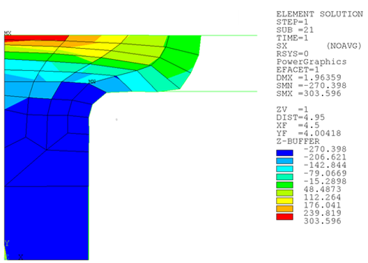
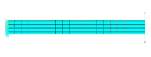
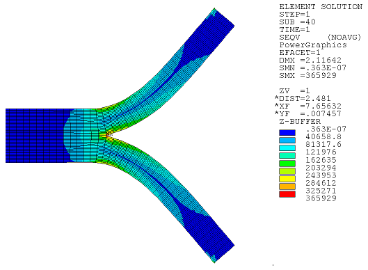
Another example of the increased accuracy achieved with nonlinear mesh adaptivity involves mesh refinements in regions with high stress concentrations. For example, consider this material cracking model:
Following is the program output for the crack simulation:
The solution and solution time are:
| σx | σy | τxy | σ_VM | Elapsed Time |
|---|---|---|---|---|
| 214113 | 91103.2 | 91641.2 | 244606 | 12.00 |
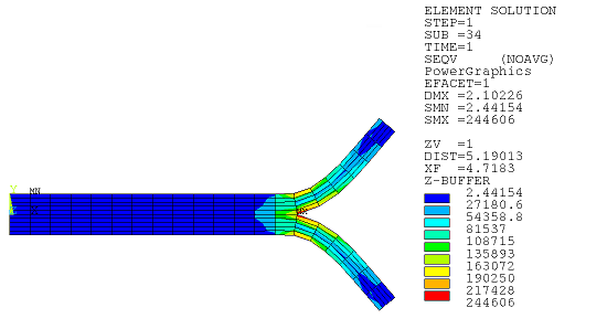
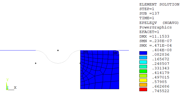
For a more accurate solution at the crack tip, nonlinear adaptivity is applied using energy-based criteria. Following is the output when three refinements are applied during solution:
The solution and solution time are:
| σx | σy | τxy | σ_VM | Elapsed Time |
|---|---|---|---|---|
| 262713 | 291816 | 164471 | 361413 | 64 |
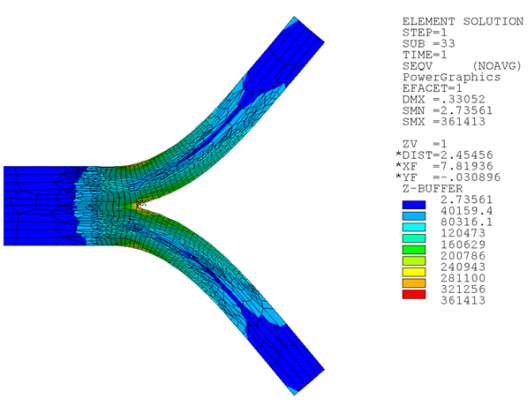
Following is the output if the same simulation is performed with a fine mesh and no nonlinear mesh adaptivity:
The solution and solution time are:
| σx | σy | τxy | σ_VM | Elapsed Time |
|---|---|---|---|---|
| 293992 | 274278 | 160033 | 365929 | 190 |
As demonstrated, nonlinear adaptivity provides sufficient accuracy, yet with drastically reduced simulation time.
Example Input: Crack Simulation
/batch,list
/prep7
! MATERIAL PROPERTIES
et,1,183
keyopt,1,1,0
keyopt,1,6,1
MP,PRXY,1,0.3
MPTEMP,1,0,500            ! Define temperatures for Young's modulus
MP,EX,1,12E6,-8E3         ! C0 and C1 terms for Young's modulus
TB,BKIN,1,2               ! Activate a data table
TBTEMP,0.0                ! Temperature = 0.0
TBDATA,1,44E3,1.2E6       ! Yield = 44,000; Tangent modulus = 1.2E6
TBTEMP,500                ! Temperature = 500
TBDATA,1,29.33E3,0.8E6    ! Yield = 29,330; Tangent modulus = 0.8E6
TBLIST,BKIN,1             ! List the data table
/XRANGE,0,0.01            ! X-axis of TBPLOT to extend from varepsilon=0 to 0.01
TBPLOT,BKIN,1             ! Display the data table

! GEOMETRY
blc4,0,0,10,0.5
blc4,0,0,10,-0.5
lsel,s,loc,y,0
lsel,a,loc,y,0.5
lsel,a,loc,y,-0.5
lesize,all,,,20
lsel,inve
lesize,all,,,5

amesh,all
elist
allsel,all

nsel,s,loc,y,0
nsel,r,loc,x,0,7
nummrg,node
allsel,all
! COMPONENT
esel,all
cm,cm1,elem
allsel,all

esel,all
cm,cm2,elem
allsel,all

! LOADS
nsel,s,loc,x,0
d,all,all
allsel,all

nsel,s,loc,y,0.5
nsel,r,loc,x,10
f,all,fy,5500
allsel,all

nsel,s,loc,y,-0.5
nsel,r,loc,x,10
f,all,fy,-5500
allsel,all

nplot
finish
/solu
nlgeom,on                       ! large displacement analysis ON
outres,all,all                  ! all solutions are written
rescontrol,define,all,all       ! write every substeps in a file
eresx,no                        ! no interpolation for the point of integration
time,1
nsubst,50,100,20
/nerr,,,,1                      ! prevent the GUI for closing if no convergence

! NON LINEAR ADAPTIVITY

nlad,cm2,add,energy,mean,1
nlad,cm2,on,,,-3
allsel,all
solve
finish

! POSTPROCESSING
/post1
/out

set,last
nsel,s,loc,y,0
nsel,r,loc,x,0,7
esln,s,0,all
presol,s,eqv

finish
/exit
This example problem demonstrates how to apply nonlinear mesh adaptivity to remove mesh distortion and solve problems associated with high deformation. Unlike the two prior problems, general remeshing is necessary with the mesh-quality-based criterion applied in this problem.
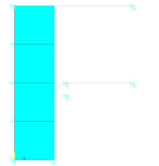
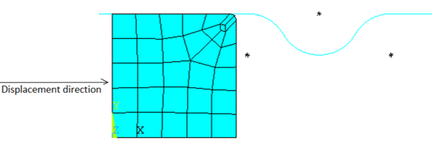
Consider a metal forging simulation, with an initial geometry and mesh:
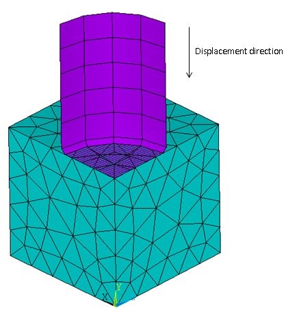
The flexible block has symmetry boundary conditions on three facets. A rigid die is placed on the top of the block with applied displacement in the Y direction. It is intended to compress the block to 80 percent. Without nonlinear adaptivity, the simulation cannot converge because of high mesh distortion, as shown:
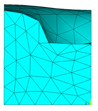
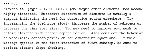
The solution diverges at approximately 40 percent load with the following error:
Nonlinear adaptivity with a mesh-quality-based criterion corrects the mesh shape caused by high distortion. To check the mesh quality at every substep, skewness is set to 0.9 (NLADAPTIVE,,,MESH,SKEWNESS,0.9). With several remeshings, the full load is successfully applied, as shown with deformation in this animation:
Example Input: 3D Metal Forging Simulation
/batch,list
/PREP7
!-----------geometry parameters---------------  !mm
cylinder_radius =   500
cylinder_offset =   1000
block_height    =   1000
radius_fillet   =   33
!---------initial meshing parameters----------
block_esize     =   200
cylinder_esize  =   200
!------------loading parameters---------------
cylinder_disp   =   -800
!------------NLAD parameters------------------
skw_            =   0.95                        !skewness threshold
freq            =   1                           !NLAD frequency (1 means check every substep)
start_time      =   0                           !beginning time for NLAD interval
end_time        =   1                           !end time for NLAD interval
!------------remeshing parameters-------------
sculpt_layers   =   4                           !no. of sculpting layers
!************material properties**************
EX=70e3
ET=7e3
EP=EX*ET/(EX-ET)
MP,EX,1,EX                                      !aluminium material properties
MP,NUXY,1,0.33                                  !poisson's ratio
MP,MU,1,0                                       !coefficient of friction
TB,PLAS,1,,,BISO                                !bilinear isotropic material
TBDATA,1,20                                     !yield stress in MPa
TBDATA,2,EP                                     !tangent modulus in MPa

!------------geometry creation----------------
blc4,0,0,block_height,block_height,block_height
k,9,0,cylinder_offset,0
k,10,0,cylinder_offset,cylinder_radius
k,11,0,cylinder_offset+cylinder_offset,cylinder_radius
k,12,0,cylinder_offset+cylinder_offset,0
l,9,10
l,10,11
l,11,12
l,12,9
lfil,13,14,radius_fillet
al,13,17,14,15,16
vrotat,7,,,,,,9,12,90

!---------element types & settings------------
et,1,285
et,2,170
et,3,174
!-------------general meshing-----------------
type,1
mat,1
real,1
esize,block_esize
vmesh,1
!-------------contact pair 1------------------
real,2
!---------------target elements---------------
type,2
mat,2
asel,s,area,,8,10
aesize,all,cylinder_esize
amesh,all
alls
!---------------contact elements--------------
type,3
mat,1
asel,s,area,,4
nsla,s,1
esln
esurf
alls
!--------------create components--------------
esel,s,ename,,285
cm,comp1,elem                                   !create NLAD component
alls
!-----boundary conditions & loading-----------
asel,s,area,,5,6
nsla,s,1
d,all,ux,0.0
alls
asel,s,area,,1,2
nsla,s,1
d,all,uz,0.0
alls
asel,s,area,,3
nsla,s,1
d,all,uy,0.0
alls
asel,s,area,,7,12
nsla,s,1
d,all,uz,0.0
d,all,ux,0.0
d,all,uy,cylinder_disp
alls
fini

/SOLU
!-----------general solution settings---------
nlgeom,on
eresx,no
outres,all,all
!---------------NLAD settings-----------------  !check NLAD parameters section above for values
nlad,comp1,add,mesh,skew,skw_                   !nlad with mesh-quality-based criterion
nlad,comp1,on,,,freq,start_time,end_time
!------------remeshing settings---------------  !check remeshing parameters section above for values
nlmesh,nlay,sculpt_layers
!---------------step settings-----------------
time,1
nsubst,100,10000,10

alls
solve
fini

!---------------POSTPROCESSING----------------
/POST1
set,list
fini
/exit
This example problem demonstrates the benefits of nonlinear mesh adaptivity for simulating cases with very high deformation. The 2D problem uses a generalized plane strain extrusion model.
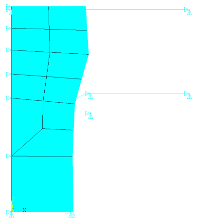
The flexible block of height = 19.5 will be compressed on the right side by a rigid die (where applied displacements = 30) to reduce its height to 6.5:
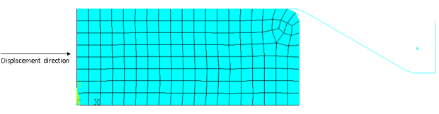
The bottom of the block has a symmetric boundary condition, the die is a frictionless rigid, and the material is elastoplastic.
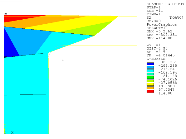
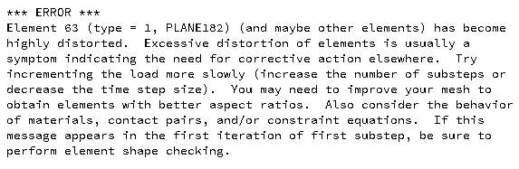
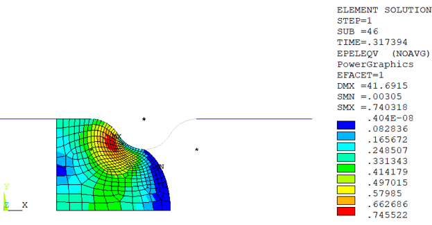
Without nonlinear adaptivity, the solution diverges at approximately 80 percent load due to mesh distortion, generating the following error message:
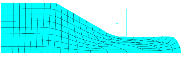
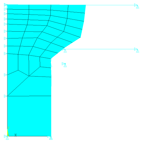
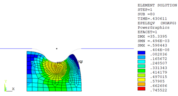
Nonlinear adaptivity with a mesh-quality-based criterion corrects a highly deformed mesh shape. To check the mesh quality at every substep, the maximum corner angle of the mesh shape is set to 155 (NLADAPTIVE,,,MESH,SHAPE,155). With several remeshings (depending on the platform), the full load is successfully applied:
Example Input: 2D Metal Extrusion Simulation
/batch,list

/PREP7
h1=19.5
b1=45
h2=6.5
b2=22.5
b3=5
h3=17
el=h1/8

et,1,182
keyopt,1,3,5
keyopt,1,6,1

EX=1.0e+6
ET=1.0e4
EP=EX*ET/(EX-ET)
mp,ex,1,1.0e+6
mp,nuxy,1,0.3
tb,plas,1,,,biso
TBDATA,1,8.0e2,EP

/com --- Rigid target
k,1,0,h1
k,2,b1,h1
k,3,b1+b2,h2
k,4,b1+b2+b3,h2
k,5,b1+b2+b3,h3

l,1,2
l,2,3
l,3,4
l,4,5
LFILLT,1,2,5, ,
LFILLT,2,3,5, ,
/pnum,line,1

/com --- Rectangular block
k,10,0,0
k,11,b1,0
k,12,b1,h1
k,13,0,h1
l,10,11
l,11,12
l,12,13
l,13,10
lfillt,8,9,el
al,7,8,11,9,10
esize,el
real, 1
mat, 1
type, 1
amesh, 1

/com --- Element type definitions for contact pair
et,2,169
et,3,172

/com --- Mesh target surface
mat, 2
real, 2
type, 2
lmesh,1,6

/com --- Create contact elements
type,3
real, 2
lsel, s, line, , 8,9
lsel, a, line, , 11
nsll,,1
esln,,0
esurf
alls

/com --- Apply Constraints

nsel,s,loc,y
d,all,uy,0.0
alls

lsel,s,line,,1,6
nsll,,1
d,all,all,0.0
alls

nsel,s,loc,x
d,all,ux,30
alls

esel,s,ename,,182
cm,c1,elem                      !create NLAD component
alls
fini

/SOLU
nlgeom,on
eresx,no
pred,off
outres,all,all

time,1
NSUBST,20,1000,5
alls

gsgdata,2,0,0,0,0
gsbdata,lfiber,0,rotx,0,roty,0
gslist,geometry
gslist,bc
alls

!-----Nonlinear Adaptive Region
cmsel,all
nlad,c1,add,mesh,shape,160,10,70  !nlad with mesh-quality-based criterion
nlad,c1,on,,,1,0,1

nlmesh,nlay,100                 !no. of sculpting layers
nlmesh,grad,0                   !option for mesh gradient control
nlmesh,srat,0.9                 !control global sizing of new mesh

nlad,all,list,all
nlmesh,list

alls
SOLVE
fini

/POST1
set,list
fini
/exit
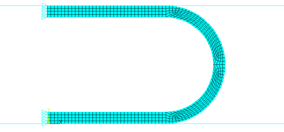
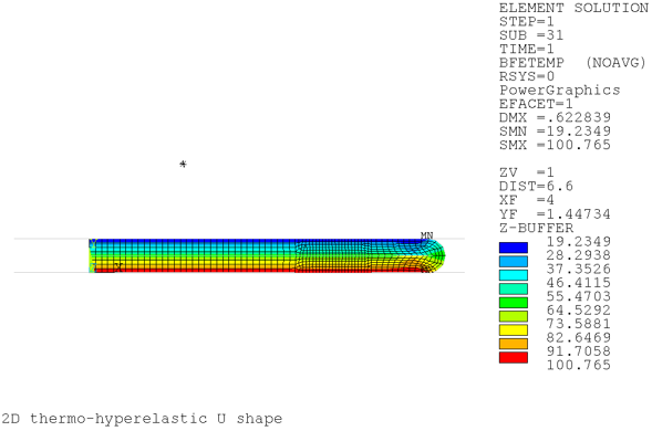
This example problem using nonlinear mesh adaptivity simulates high mesh-deformation with coupled structural-thermal degrees of freedom. The analysis uses the 2D coupled-field element PLANE222 with structural-thermal coupling and plane strain options.
A U-shape workpiece is compressed between two rigid and frictionless target surfaces. The top target surface is displaced in the negative y direction to compress the workpiece to reach a state of complete self-contact. A temperature difference is applied on the top and bottom surfaces. Temperature-dependent thermal material properties are defined in the model.
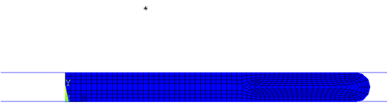
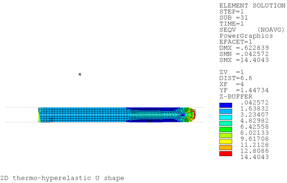
Without nonlinear adaptivity, the highly deformed mesh shape leads to a diverged solution. A mesh-quality-based criterion defined by nonlinear adaptivity measures the mesh quality and verifies a maximum corner angle of 150 degrees (NLADAPTIVE,ADD,,MESH,SHAPE,150) at every substep. With refined meshing, the solution can converge with the total displacement load applied.
Example Input: Compression of 2D Thermo-Hyperelastic U-Shape Simulation
/batch,list
/title, 2D thermo-hyperelastic U shape

/prep7
/nopr

h=0.5
b = 4
x0 = 0.0
y0 = 0.0
x1 = 5.0
y1 = x0+h
y2 = x0+h+b

et,1,222,11
keyo,1,3,2
keyo,1,11,1

tb,hype,1,1,3,ogde
tbdata,1,3.2084e-009,7.281,0.035198,3.0149,6.3712,2.0493

mptemp,1,100,200,300,400,500
mpdata,alpx,1,1,2.568e-6,3.212e-6,3.594e-6,3.831e-6,3.987e-6
mpdata,kxx,1,1,14.64,9.83,7.32,5.75,4.92

! upper contact pair
et,2,169
r,2

et,3,172
keyo,3,1,1        ! ux/uy/temp
keyo,3,9,0
keyo,3,10,0

mp,mu,2,0.0

! lower contact pair
et,4,169
r,3

et,5,172
keyo,5,1,1        ! ux/uy/temp
keyopt,5,9,0
keyopt,5,10,0

mp,mu,3,0.0

! self-contact pair
et,6,169
r,4
rmodif,4,14,10.0
et,7,172
keyo,7,1,1        ! ux/uy/temp
keyopt,7,9,0
keyopt,7,10,0

mp,mu,4,0.0

et,8,169
r,5
rmodif,5,14,10.0
et,9,172
keyo,9,1,1        ! ux/uy/temp
keyopt,9,9,0
keyopt,9,10,0

mp,mu,5,0.0

! Geometry

! keypoints
k, 1, x0, y0
k, 2, x1, y0
k, 3, x0, y0+h
k, 4, x1, y0+h

k, 5, x0, y2
k, 6, x1, y2
k, 7, x0, y2+h
k, 8, x1, y2+h

k, 9, x1, y0+h+b/2
k, 10, x1, y0+h+b/2, y0+h+b/2
circle, 9, , 10, 4, 180
circle, 9, , 10, 2, 180

! line definitions
l, 1, 14
l, 3, 11
l,1, 3
l, 13, 5
l, 16, 7

l, 5, 7

l,11,14
l,13,16

l,12,15

! area definitions
al,5,11,6,7
al,3,13,1,11
al,4,12,2,13
al,8,12,9,10

esize,0.15
real,1
mat,1
type,1
amesh,all

asel,s,area,,2,3
esla,s
esel,r,type,,1
cm,cm222,elem
alls

! contact definitions
k, 17, x0-2.0, y0
k, 18, x1+5.0, y0

k, 19, x0-2.0, y0+h+h+b
k, 20, x1+5.0, y0+h+h+b

l, 18, 17
l, 19, 20

! 1st contact pair -- top surface pair
mat,2
real,2
type,2

! mesh target surface
lmesh,15

! define pilot node
*get,PilotKpt,kp,,num,max
PilotKpt=PilotKpt+1
k,PilotKpt,x0+x1/2,y0+h+h+b+2.0
*get,PilotID,node,,num,max
PilotID=PilotID+1
nkpt,PilotID,PilotKpt
tshap,pilo
e,PilotID

! define contact elements
type,3
real,2
lsel,s,line,,4
lsel,a,line,,9
nsll,,1
esln,,0
esurf
alls

! second contact pair --- bottom pair
mat,3
type,4
real,3

! mesh target surface
lmesh,14

! mesh contact elements
type,5
real,3

lsel,s,line,,5
lsel,a,line,,3
nsll,,1
esln,,0
esurf
alls

! 1st self-contact pair
mat,4
type,6
real,4
lsel,s,line,,6,8,2
nsll,,1
esln,,0
esurf
alls

type,7
real,4
lsel,s,line,,6,8,2
nsll,,1
esln,,0
esurf
alls

! 2nd self-contact pair
mat,5
type,8
real,5
lsel,s,line,,1,2
nsll,,1
esln,,0
esurf
alls

type,9
real,5
lsel,s,line,,1,2
nsll,,1
esln,,0
esurf
alls

! Initial boundary conditions
d,PilotID,ux,0.0
d,PilotID,uy,-4.1
d,PilotID,rotz,0.0

nsel,s,loc,x,0.
d,all,ux,0.
alls

tref,20.0

DL,14,,temp,100
DL,15,,temp,500
alls

cnch,auto
rmodif,4,14,1000.0
rmodif,5,14,1000.0
fini

/solu
/nopr
nlad,cm222,add,mesh,shape,150
nlad,cm222,on,,,1

nlmesh,nlay,10
nlmesh,srat,0.8
nlmesh,bdra,10
nlmesh,grad,2

nlgeom,on
eresx,no
time,1
nsub,20,100,5
rescontrol,define,all,all
outres,all,all
solve
fini

/post1
set,list
finish
/exit,nosave
This example demonstrates the benefits of nonlinear adaptivity with mesh coarsening in addition to mesh refinement and mesh-quality improvement. The 2D problem uses a hyperelastic material (rubber) which is pushed from the left through a narrow channel. The bottom of the block has a symmetric boundary condition. The contact to the channel has friction.
During the analysis, the mesh is adapted to improve the quality of deformed elements and the solution quality in regions of interest (high strain energy). Without nonlinear adaptivity, the solution diverges due to mesh distortion, when the rubber is deformed upon entering the narrow channel (at approximately 30 percent of applied load).
At the end of the analysis, the mesh is adapted to reduce the numerical effort (coarsening the mesh) for elements that have passed the narrow channel and where a refined mesh is no longer required to obtain a high-quality solution.
Example Input: 2D Rubber Extrusion Simulation
/batch,list

/prep7

/com, --- Geometry parameters
ly=100
lx=ly
g0=0.1*lx
l2=1.5*lx
gy=0
rad=ly/3
rad0=rad            !fillet radius of the rigid target
rad1=5              !fillet radius of the solid
g1=rad0             !g1 has to be min rad0 due to fillet

/com, --- Meshing parameters
es=20               !general element size
div=2               !nb divisions per solid fillet

/com, --- Material parameter
tb,hyper,1,,2,ogden     !td2 values
tbdata,1,2.8
tbdata,2,7.9
tbdata,3,-1.86e2
tbdata,4,-1.85
tbdata,5,1.e-5          ! incompressibility parameter

mp,mu,2,0.1         ! fric coeff for contact elements

/com, --- Element definition
et,1,182
keyopt,1,1,0            ! full integration Bbar method
keyopt,1,3,2            ! plane strain
keyopt,1,6,1            ! mixed u-p formulation

et,2,172
keyopt,2,10,2           ! cont. stiffness update: each iteration
keyopt,2,15,3           ! cont. stabilization: damping active

et,3,169
/com, --- Contact real constants
pinb=1.0            !scale factor for the default pinball size
r,11,,,,,,pinb
r,12,,,,,,pinb

/com, --- Geometry
k,1,0,0
k,2,lx,0
k,3,lx,ly
k,4,0,ly

k,5,-g0,ly+gy
k,6,lx+g1,ly+gy
k,7,lx+g1+rad,ly-rad+gy
k,8,lx+g1+2*rad,ly+gy
k,9,lx+g1+2*rad+l2,ly+gy
k,11,lx+g1+rad,ly+gy

k,10,0,0
k,12,0,ly+gy

l,1,2
l,2,3
l,3,4
l,4,1
l,5,6
larc,6,7,11,rad
larc,7,8,11,rad
l,8,9

lfillt,5,6,rad0
lfillt,7,8,rad0

l,10,12
lfillt,2,3,rad1          ! solid fillet
al,1,2,12,3,4           ! single fillet

/com, --- Meshing
type,1
esize,es
mshape,0,2-D            ! 0-Quadrilaters

lsel,s,line,,12             ! single solid fillet
lesize,all,,,div
amesh,all

mat,2
real,11
type,2
lsel,s,line,,2,4,1
lsel,a,line,,12
nsll,s,1
esurf
allsel
type,3
lmesh,5,10,1
ldele,11

/com, --- Boundary conditions
esel,s,type,,1
nsle,s,all
nsel,r,loc,y
d,all,uy

esel,s,type,,1
nsle,s,all
nsel,r,loc,x
cm,my_nodes,node
allsel
cmsel,all
finish

/com, --- Solution parameters
/solution
antype,static
nlgeom,on
outres,all,all
rescontrol,define,all,1
eresx,no
nropt,unsym,,off
time,1
pred,off
nsubst,10000,100000,100
cmsel,s,my_nodes
d,all,ux,225
allsel
cmsel,all

/com, -- Nonlinear Adaptivity settings
esel,s,type,,1          ! all solid elements
cm,cm2enrg,elem         ! Refinement
cm,cm2coar,elem         ! Distortion
cm,cm2mesh,elem         ! Coarsening
allsel
cmsel,all

nlad,cm2enrg,add,energy,mean,1.e-10
nlad,cm2enrg,on,,,-2,0,0.3

nlad,cm2mesh,add,mesh,shape,150
nlad,cm2mesh,on,,,1

nlad,cm2coar,add,box,xyzr,225,300,0,100,,,coar
nlad,cm2coar,on,,,-5,0.7,1.

nlmesh,nlay,7,3
nlmesh,srat,,,2.

allsel
cmsel,all

/com, --- Solution process
solve
finish