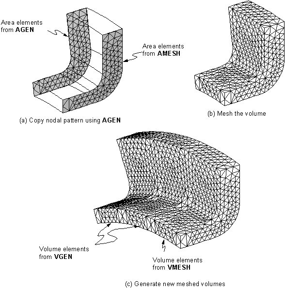
In the normal solid modeling procedure, you will ordinarily complete your entire solid model before generating your finite element mesh. However, if repetitive geometric features appear in your model, you might sometimes find it more efficient to model and mesh just one representative portion of your model, and then copy that meshed region as many times as needed to complete the model. (It is usually much less expensive to copy an existing mesh than to generate a new mesh.) A certain amount of forethought is generally required if you are to accomplish this procedure successfully.
The general procedure for copying a meshed region is to use the commands for generating and transferring areas and volumes, which are described below. When a meshed solid model entity is copied using one of these commands, all the attached lower-order entities, as well as the node and element mesh, are copied along with that entity.
To generate additional areas from a pattern of areas, use the AGEN command.
To generate additional volumes from a pattern of volumes, use the VGEN command.
To generate areas from an area pattern by symmetry reflection, use the ARSYM command.
To generate volumes from a volume pattern by symmetry reflection, use the VSYMM command.
To transfer a pattern of areas to another coordinate system, use the ATRAN command.
To transfer a pattern of volumes to another coordinate system, use the VTRAN command.
You must plan ahead to ensure that the interfaces between copied regions will match up node for node. For example, if you freely meshed a volume, the pattern of nodes on the right end would not necessarily match the pattern of nodes on the left end. If the original part and its copy were to be joined such that the right end of one part interfaced with the left end of the other part, a seam of discontinuity would be created where the two mismatched faces touched.
It is relatively easy to create matching node patterns along the line edges of meshed areas: simply specify the same number of line divisions and division spacings on both sides of the original part. Volumes are not so straightforward, however. You will need to use a trick to force matching node patterns on two faces of a meshed volume. Before meshing with volume elements, mesh one of the matching faces with dummy area elements, then copy that meshed area to the other matching face. (Depending on how you originally created your volume, you might or might not have some cleaning up to do at this point. If you wind up with duplicate coincident areas, you should redefine your volume in terms of the new meshed area, and delete the original volume.) The volume can then be meshed with solid elements. After the volume meshing is complete, you should delete the dummy area elements. (You can do this fairly cleanly using selecting and the ACLEAR command.)
Having created meshed regions which will match up at their interfaces, you can now copy the part, such that the repeated regions just touch. Even though these regions will have matching nodes at the interfaces, the degrees of freedom at these nodes will remain independent. That is, a seam of discontinuity will exist in your model at the interface. You should execute NUMMRG,ALL to eliminate this discontinuity. It is usually good practice to follow these operations with a NUMCMP command.


