There are generally two situations in which you may want to refine a mesh in a local region:
You have meshed a model and you would like a finer mesh in specific regions of the model, or
You have completed the analysis and, based on the results, would like a more detailed solution in a region of interest.
For all area meshes and for volume meshes composed of tetrahedra, the Mechanical APDL program allows you to refine the mesh locally around specified nodes, elements, keypoints, lines, or areas. Meshes composed of volume elements other than tetrahedra (for example, hexahedra, wedges, and pyramids) cannot be locally refined.
The following mesh-refinement topics are available:
You must follow these two steps to refine a mesh:
Select the entity (or set of entities) around which refinement will be done.
Specify the level of refinement to be done (in other words, the desired size of the elements in the refinement region, relative to the size of the original elements). The refined elements will always be smaller than the original elements. The local mesh refinement process does not provide mesh coarsening (
LEVEL).
If you prefer to have more control over the refinement process, you can also set values for any of the following advanced options:
You can specify the depth of the mesh refinement region in terms of the number of elements outward from the indicated entities (
DEPTH).You can specify the type of postprocessing to be done after the original elements are split. Postprocessing may include both smoothing and cleaning, smoothing only, or neither one (
POST).You can specify whether triangles can be introduced into the mesh during the refinement of an otherwise all-quadrilateral mesh. In other words, you can indicate whether quadrilateral elements must be retained (
RETAIN).
Use the following xREFINE commands and menu paths to select entities for refinement and to set refinement controls. (The refinement controls are described in detail below.)
To refine around a selected set of nodes, use the NREFINE command.
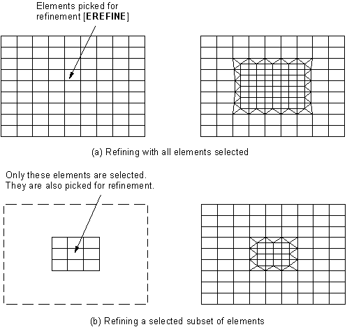
To refine around a selected set of elements, use othe EREFINE command.
To refine around a selected set of keypoints, use the KREFINE command.
To refine around a selected set of lines, use the LREFINE command.
To refine around a selected set of areas, use the AREFINE command.
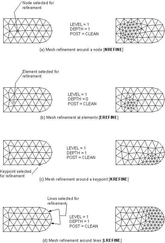
Figure 8.1: Examples of Local Mesh Refinement shows examples of mesh refinement around a node (NREFINE), element (EREFINE), keypoint (KREFINE), and line (LREFINE).
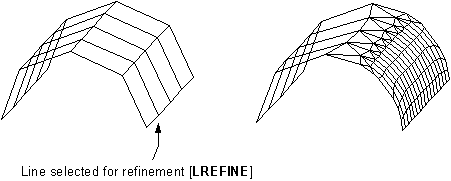
Figure 8.2: Tetrahedral Mesh Refinement Around an Area illustrates the use of the AREFINE command to perform tetrahedral mesh refinement around an area.
Use the LEVEL argument to specify how much
refinement is to be done. The value of LEVEL must be
an integer from 1 to 5, where a value of 1 provides minimal refinement, and a
value of 5 provides maximum refinement. When LEVEL =
1, the resulting element edges in the refined region are approximately 1/2 the
original edge lengths. When LEVEL = 5, the resulting
element edges are approximately 1/9 the original edge lengths. The table below
lists all of the possible settings of LEVEL, along
with the approximate resulting edge length for each setting.
| Value of LEVEL Argument | Approximate Edge Length |
|---|---|
| 1 | 1/2 |
| 2 | 1/3 |
| 3 | 1/4 |
| 4 | 1/8 |
| 5 | 1/9 |
Values of LEVEL from 1 to 5 attempt to provide
gradually decreasing element edge lengths. However, be aware that when
RETAIN = ON, different values of
LEVEL may provide the same refinement. (For more
information, see the explanation of the RETAIN
argument below.) Elements in the layer just outside of the refinement region
(that is, beyond the specified DEPTH) may also be
split in order to transition to the refinement elements.
Note: All values of LEVEL result in smaller elements
in the refinement region. The local mesh refinement process does not provide
mesh coarsening.
By default, the mesh is refined one element outward from the chosen entities
(except for element refinement, which uses DEPTH = 0
as the default), and the elements are split one time (that is, the element edges
are divided in half, since LEVEL = 1 by
default).
As part of the refinement process, you can specify the type of postprocessing Mechanical APDL does after the original elements are split. You can choose smoothing and cleaning (the default), smoothing only, or neither one.
If you want Mechanical APDL to do smoothing and cleaning, set
POST= CLEAN (or choose Cleanup & Smooth in the GUI).If you want Mechanical APDL to do only smoothing, set
POST= SMOOTH (or choose Smooth in the GUI).If you do not want Mechanical APDL to do either type of postprocessing, set
POST= OFF (or choose Off in the GUI).
Smoothing: By default, nodes in the refinement region are smoothed (that is, their locations are adjusted) to improve the element shapes. Node locations will be adjusted subject to the following constraints:
Nodes at keypoints will not move.
Nodes on lines will move only on the line.
Nodes within areas will remain on the surface.
If the mesh has been detached from the solid model (MODMSH,DETACH), smoothing will not be done.
You can turn node smoothing off for all nodes by setting
POST = OFF for the refinement command being used.
(Doing so turns cleanup off as well.)
Cleanup: When cleanup
is turned on (POST = CLEAN), the Mechanical APDL program
performs cleanup operations (in 2D models) on all of the elements that are
associated with any affected geometric entities. In 3D models, Mechanical APDL performs
cleanup only on those elements that are in or directly adjacent to the
refinement region. Cleanup operations improve the quality of the elements. If
the mesh has been detached from the solid model,
(MODMSH,DETACH), cleanup will not be done on area meshes, but
it will be done on tetrahedral volume meshes.
When you are refining a quadrilateral mesh, cleanup operations attempt to
eliminate triangles from the refinement transition region. If poorly-shaped
quadrilateral elements remain after the cleanup operations have optimized
element quality, Mechanical APDL splits the elements into triangles. You can prevent
this splitting of quadrilateral elements by setting
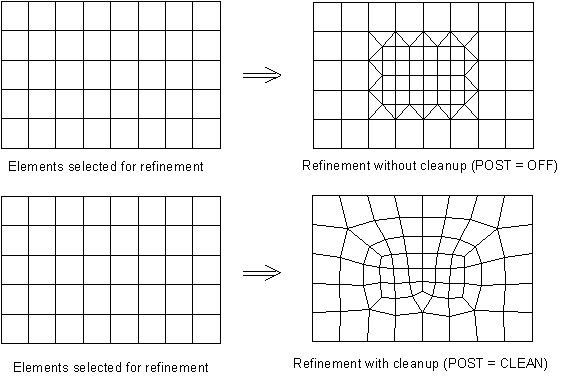
RETAIN = ON (the default). Figure 8.3: All-Quadrilateral Mesh illustrates the cleanup of an all-quadrilateral
mesh.
Note: You can turn cleanup off by setting POST = OFF or POST = SMOOTH for the refinement command being used.
Note: The Mechanical APDL program ignores the RETAIN
argument when you are refining anything other than a quadrilateral
mesh.
By default, RETAIN = ON, which means that the
refinement process will not introduce triangular elements into an otherwise
all-quadrilateral mesh. When RETAIN = OFF and
POST = SMOOTH or OFF, the resulting refinement
region may contain triangles in order to maintain transitioning. When
RETAIN = OFF and POST
= CLEAN, triangles are minimized. However, they may not be completely eliminated
- a minimal number of triangles may remain in the transition region in order to
provide good element quality.
Note: If an area is meshed with a mixture of quadrilateral and triangular
elements, the quadrilateral elements will not be maintained in the
refinement region even when RETAIN = ON.
Since quadrilateral meshes are much more constrained than triangular meshes,
increasing or decreasing the value of the LEVEL
argument may not provide the desired increase or decrease in the level of
refinement when RETAIN = ON. In addition, even when
quadrilateral elements can be maintained, the quality of some of them may be
poor, especially with a higher value of LEVEL. By
setting RETAIN = OFF, however, some triangles may be
introduced into the mesh. This may not be desirable, especially if you are using
lower-order elements. You can keep these triangles out of the point of interest
by doing one of the following:
Refine with a larger
DEPTH; that is, at a larger radius from the point of interest.Refine with
POST= CLEAN. This setting for thePOSTargument minimizes the number of triangles as much as possible.Refine using another method (for example, use local mesh controls and remesh).
Element attributes associated with the "parent" element are automatically transferred to all of the "child" elements. These attributes include element type, material properties, real constants, and element coordinate systems (see Generating the Mesh for details on element attributes).
Loads and boundary conditions applied to the solid model are transferred to nodes and elements when the solution is initiated (or when loads are manually transferred with the SBCTRAN or DTRAN commands). Therefore, solid model loads will be correctly applied to the new nodes and elements created during refinement. However, loads and boundary conditions applied at the node and element level (finite element loads) cannot be transferred to new nodes and elements created during refinement. If you have such loads in a region selected for refinement, the program will not allow refinement to take place unless the loads are first deleted. Therefore, Ansys recommends that you apply loads only to the solid model rather than directly to nodes and elements if you anticipate using mesh refinement.
Other characteristics of mesh refinement include the following:
The new elements and nodes created during refinement (including midside nodes) are projected to the underlying solid model geometry. (See Figure 8.4: Nodes and Elements are Projected to Underlying Geometry.)
When using the option to refine around nodes (NREFINE), midside nodes that are included in the selected set are ignored.
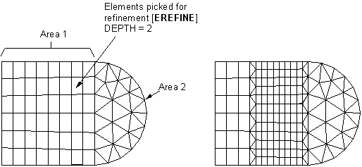
Mesh refinement will not cross area and volume boundaries. That is, if the specified
DEPTHgoes beyond the edges of the meshed area or volume, the adjacent area and/or volume meshes won't change (see Figure 8.5: Mesh Refinement Will Not Cross Area Boundaries). However, if an entity picked for refinement (node, element, keypoint, or line) is on the boundary, or entities are picked on both sides of the boundary, then refinement will extend into the adjacent area or volume.Mesh refinement will take place only in elements that are currently selected (see Figure 8.6: Only Selected Elements are Refined).
Refinement can be used on a mesh that has been detached from the solid model (MODMSH,DETACH or menu path ). In this case, the refinement will not be stopped by area boundaries. Also, the nodes and elements will not be projected to the solid model and none of the postprocessing specified with the
POSTargument will be done.When cleanup is turned on (
POST= CLEAN) during the refinement of a tetrahedral mesh, Mechanical APDL automatically performs a high level of cleanup operations (that is, a level equivalent to VIMP,,,2) in the refinement region only. If you receive shape error messages during refinement, turn off shape checking (SHPP,OFF), perform refinement again (xREFINE), and then request tetrahedral element improvement at the highest level (VIMP,,,3).If you use the LESIZE command to specify divisions for lines and those lines are later affected by the refinement process, Mechanical APDL changes the line divisions for the affected lines (that is, the numbers of divisions on the lines not only increase, but also show up as negative numbers in a subsequent line listing (LLIST)).
Note: The presence of the negative sign affects how Mechanical APDL treats the line divisions if you clear the mesh later (ACLEAR, VCLEAR, etc.). If the number of line divisions is positive, Mechanical APDL does not remove the line divisions during the clearing operation. If the number is negative, Mechanical APDL removes the line divisions (which will then show up as zeros in a subsequent line listing).
The following restrictions apply to mesh refinement:
Although local refinement can be used for all area meshes, it can be used for only those volume meshes that are composed of tetrahedra. Meshes composed of volume elements other than tetrahedra (for example, hexahedra, wedges, and pyramids) cannot be locally refined.
If the model contains contact elements in the region selected to refine, you cannot use local mesh refinement. In this case, refine the mesh before defining contact elements (or, delete the contact elements, refine the mesh, then reapply the contact elements).
Local mesh refinement does not support elements that are generated on the free faces of existing elements (ESURF). Instead of using refinement on these elements, delete the surface elements, refine the underlying elements, and then generate the surface elements again.
If beam elements exist adjacent to the refinement region, refinement cannot be done. In order to refine in this area, the beam elements should be deleted and redefined after refinement is performed.
If loads are applied directly to the nodes and elements in a model, refinement cannot be done. In this case, you must delete the loads in order to refine the mesh. (To avoid this situation, it is recommended that you apply loads to the solid model instead of the finite element model.)
Local mesh refinement cannot be done if initial conditions at nodes (IC), coupled nodes (CP family of commands), or constraint equations (CE family of commands) exist in the model. If any of these exist, you must remove them before refinement can be done.
The KSCON command is not supported. For any area that was meshed with the KSCON command, midside nodes will be placed at the middle of the edges when refinement is done.
If element or node components are defined, you are asked whether you want to proceed with the refinement. If you choose to proceed, you must update any affected components.


