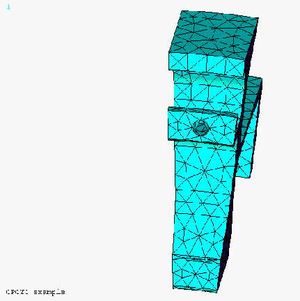
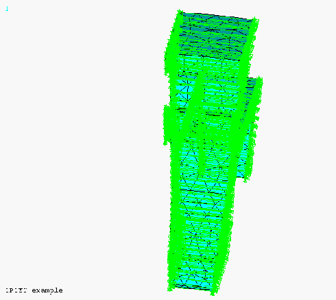
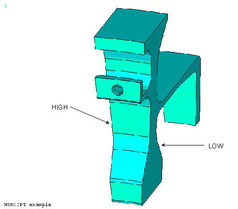
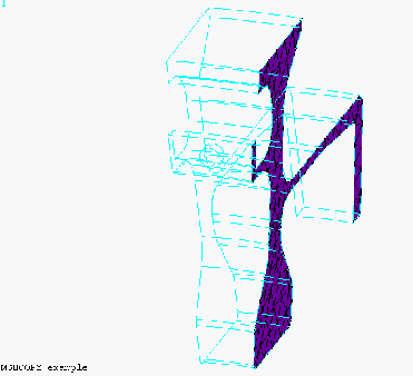
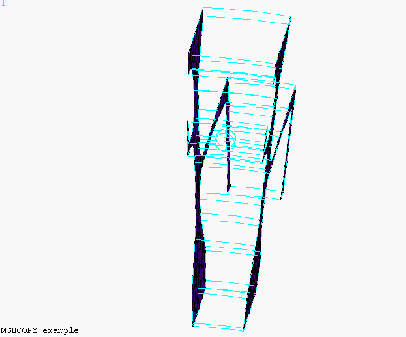
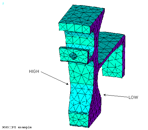
The cyclic sector model shown below represents 1/20 (18° of arc) of a disk. For loadings which are the same on every sector, you can obtain a correct solution by coupling the degrees of freedom on the "low" sector boundary and the corresponding DOF on the "high" boundary. Cyclic sector models are typically referred to the global cylindrical coordinate system. Moving from the "low" boundary in the +θ direction passes through the sector toward the "high" boundary. Cyclic coupling requires identical node and element patterns on the low and high sector boundaries. The MSHCOPY operation allows convenient generation of such a matching mesh.
The CPCYC operation will couple the DOF on the low boundary to the corresponding DOF on the high boundary. It will also rotate the nodal DOF into the cylindrical system you use to specify the angle spanned by the sector. (This is needed to couple radial deflection to radial deflection, axial to axial, and circumferential to circumferential.)
The cyclic sector model shown below represents 1/20 (18° of arc) of a disk.
If loads are symmetric about the cut planes, the left and right faces can be treated as symmetry surfaces. In such cases, equally good results could be obtained by slicing the model in half through the center of the hole, including only 9° of arc.
For more complex loadings, or for cyclic sector models having non-flat cut surfaces, symmetry boundary conditions are not correct, and may produce misleading results. There are several approaches to obtaining correct solutions for such cases, all of which require establishing a relationship between solution degrees of freedom on the "low" sector boundary and corresponding DOF on the "high" boundary. (Cyclic sector models are typically referred to the global cylindrical coordinate system. Moving from the "low" boundary in the +θ direction passes through the sector toward the "high" boundary. For example, see CPCYC.) These methods all require identical node and element patterns on the low and high sector boundaries. The MSHCOPY operation allows convenient generation of such a matching mesh.
The first step is to mesh the low sector boundary areas. MESH200 is a good choice.
The second step is to use MSHCOPY to duplicate the low sector boundary elements onto the high sector boundary. If you intend to perform a modal cyclic symmetry analysis, be sure to allow MSHCOPY to create the low and high node components.
The third step is to mesh the sector volume(s). The volume elements will use the area element connectivity already in place on the sector boundaries.
The final step is to make sure that the area elements do not affect the solution. Use one of the following methods:
Use MESH200 elements to mesh the sector boundaries. They have no DOF, and cannot affect a solution, or
Clear all area elements after creating the volume mesh, or
Unselect all area elements before solution. This method will cause a warning at solution about the unselected elements. You also run the risk that someone may inadvertently activate them during a later solution using the same analysis model.


