The following examples are available:
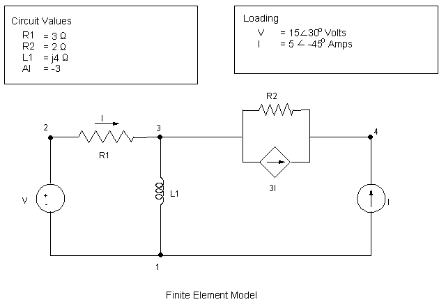
A circuit consists of two resistors, and inductor, an independent voltage source, an independent current source, and a current-controlled current source. Determine the voltage at node 4 in the circuit (Refer to the figure below).

You can perform the example AC (harmonic) circuit analysis using the Mechanical APDL commands shown below instead of GUI choices. Items prefaced with an exclamation point (!) are comments.
/BATCH,LIST
/PREP7
/TITLE, AC CIRCUIT ANALYSIS
/COM,   SEE SCHAUMS OUTLINE "BASIC CIRCUIT ANALYSIS", 2ND ED, 1992,
/NOPR
ET,1,CIRCU124,4    ! VOLTAGE SOURCE
ET,2,CIRCU124,3    ! CURRENT SOURCE
ET,3,CIRCU124,0    ! RESISTOR
ET,4,CIRCU124,1    ! INDUCTOR
ET,5,CIRCU124,12   ! CURRENT CONTROLLED CURRENT SOURCE
R,1,15,30          ! VOLTAGE SOURCE
R,2,5,-45          ! CURRENT SOURCE
R,3,3              ! R1
R,4,2              ! R2
R,5,4              ! L1
R,6,-3              ! CCCS GAIN
N,1
NGEN,10,1,1,1,1
TYPE,1
REAL,1
E,2,1,7            ! V1
TYPE,3
REAL,3
E,2,3              ! R1
TYPE,4
REAL,5
E,3,1              ! L1
TYPE,3
REAL,4
E,3,4              ! R2
TYPE,5
REAL,6
E,3,4,5,2,1,7      ! CCCS
TYPE,2
REAL,2
E,1,4              ! C1
FINISH
/SOLU
ANTYP,HARM
D,1,VOLT,0
PI=4*ATAN(1)
HARFRQ,1/(2*PI)
OUTPR,ALL,ALL
HROUT,OFF
SOLVE
FINISH
/POST1
SET,1,1                 ! READ IN REAL SOLUTION
PRESOL,ELEM             ! PRINT CIRCUIT SOLUTION PER ELEMENT
SET,1,1,,1              ! READ IN IMAGINARY SOLUTION
PRESOL,ELEM             ! PRINT CIRCUIT SOLUTION PER ELEMENT
FINISH
Target Solution, Node 4: V = 14.44 -j 1.41
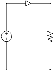
The following input listing is for a half wave rectifier circuit using an ideal diode. The circuit is shown in Figure 14.10: Half Wave Rectifier Circuit.
/BATCH
/TITLE, SIMPLE HALF WAVE RECTIFIER WITH IDEAL DIODE
/NOPR

/COM	Vs = 135*SIN(2*PI*T) VOLTS

/OUT,SCRATCH
PI = 4*ATAN(1)
/PREP7
R,1,,135,1,			!SET UP SINUSOIDAL VOLTAGE SOURCE
N,1,-0.85,0.4,0
N,2,-0.85,0.25,0
RMOD,1,15,0,1
ET,1,CIRCU124,4,1
TYPE,1
REAL,1
MAT,1
!*
N,3,-0.85,0.325,0
E,1,2,3   				!CREATE IND. SINUSOIDAL VOLT SOURCE
R,2,2500,   			!SET UP 2500 OHM RESISTOR
N,4,-0.75,0.4,0
N,5,-0.75,0.25,0
RMOD,2,15,0,2
ET,2,CIRCU124,0,0
TYPE,2
REAL,2
MAT,1
E,4,5   				!CREATE 2500 OHM RESISTOR
!
! THE FOLLOWING COMMANDS ARE USED TO SET UP THE IDEAL DIODE
!
ET,3,125,
R,3
TYPE,3
REAL,3
E,1,4
!
! APPLY GROUND TO CIRCUIT
!
D,2,VOLT,0
D,5,VOLT,0
ALLS
EPLOT
FINISH
!
! SOLVE NONLINEAR CIRCUIT WITH T = 0 TO 1.5
!
/SOLU
ANTYPE,TRANS						! TRANSIENT ANALYSIS
OUTRES,ALL,ALL,
TIME,1.5
AUTOTS,1  							! AUTO TIME STEPPING
DELTIM,0.01,0.01,0.04 		! 0.01 < TIME STEPPING < 0.04
CNVTOL,VOLT						! CONVERGENCE CRITERIA
SOLVE
FINISH

/POST26
NSOL,2,4,VOLT,,
/OUT
PRVAR,2,
/AXLAB,Y,OUTPUT POTENTIAL (VOLT)
PLVAR,2,							! PLOT THE OUTPUT VOLT
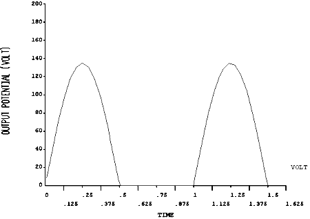
The output voltage is shown in Figure 14.11: Half Wave Rectifier Output.
The Mechanical APDL Verification Manual consists of test case analyses demonstrating the analysis capabilities of the Ansys, Inc. family of products. While these test cases demonstrate solutions to realistic analysis problems, the Mechanical APDL Verification Manual does not present them as step-by-step examples with lengthy data input instructions and printouts. However, most users who have at least limited finite element experience should be able to fill in the missing details by reviewing each test case's finite element model and input data with accompanying comments.
The following list shows you some of the test cases that the Mechanical APDL Verification Manual includes:


