The methods used to model and mesh the fluid domain depend on the squeeze film analysis method. If the velocities are directly applied to the fluid elements, the fluid elements can be independent of the structure. If the velocities are determined from the mode-frequency response of the structure (modal projection method), the fluid elements cannot be independent of the structure.
In the modal projection method, the FLUID136 elements must lie on the surface of the structural mesh. Use the ESURF command to overlay FLUID136 elements on the surface of an existing structural mesh. FLUID136 supports 4-node and 8-node options, along with degenerative triangles.
The FLUID138 element is used to model the pressure drop in the channels (holes) in a structure as shown in Figure 3.2: Perforated Plate Structure. The element supports a circular hole configuration and a rectangular hole configuration (KEYOPT(3)). The element works in conjunction with FLUID136 to correctly compute the pressure distribution on the structure's surface and through the channels. To correctly model the FLUID138 element:
Use a single FLUID138 element for each hole.
Align the FLUID138 element at the center of the hole. The element should extend through the depth of the hole and have a length equal to the depth of the hole.
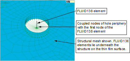
Assume the pressure at the center of the hole (flush with the plate surface in the thin film region) is at the same pressure as the nodes modeled at the periphery of the hole. Couple the nodes of the FLUID136 element at the whole periphery with the node of the FLUID138 element as shown in Figure 3.5: Coupling of Nodes at the Hole Periphery with the Center Node of a FLUID138 Element.