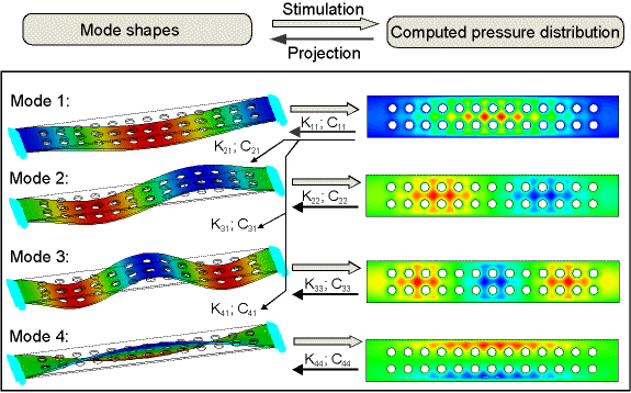
For a structure undergoing flexible body dynamics, the displacement and velocity vary along the structure. For a thin-film fluid adjacent to the structure, there is a true dependency between the structural velocity and the fluid pressure. A modal analysis of a structure provides information on the fundamental eigenfrequencies and mode shapes (eigenvectors). For each mode, i, we can impress the distributed eigenvector values as velocity loads and compute the resulting pressure distribution and hence the fluid force acting on mode j. Therefore, we can compute a matrix of modal squeeze stiffness coefficients, Kij, and modal damping coefficients, Cij. The diagonal terms of these matrices are the coefficients of each mode, the off-diagonal terms represent the "cross-talk" coefficients between modes. Figure 4.1: Modal Projection Technique for Damping Characterization illustrates the modal projection technique.
From the modal squeeze and stiffness coefficients for the main diagonal terms (source mode = target mode), other useful damping parameters can be calculated. For example, the modal damping ratio, ξ , and the modal squeeze to stiffness ratio, kri, can be computed by:

Where mi is the modal mass and ωi the eigenfrequency. The damping ratio can be used to compute ALPHAD and BETAD parameters for Rayleigh damping (see ABEXTRACT command), or to specify constant and modal damping by means of the DMPRAT or MDAMP commands.
The squeeze to stiffness ratio represents the relative stiffening of the mechanical system due to fluid compression and resonance shift. If the squeeze-to-stiffness ratio is small (for example, <.02), then the squeeze stiffness affects the structural stiffness by less than 2%, which may be negligible. At higher frequencies, the ratio can be much larger, indicating a significant stiffening of the structure.
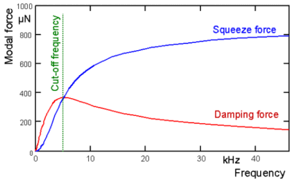
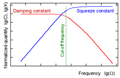
The stiffness and damping coefficients may be strongly frequency-dependent. Figure 4.2: Damping and Squeeze Stiffness Parameters for a Rectangular Plate shows a typical frequency dependency of the squeeze and damping forces on a flat plate, and the resulting stiffness and damping constant. The frequency where the forces intersect is known as the cut-off frequency. Below this frequency, structures may be accurately characterized by a constant damping coefficient, and stiffness effects can be ignored. Structures which operate far above the cut-off can be described by a constant stiffness coefficient, and damping effects can be ignored.