


These procedures assume that you are running a supported version of NX and Mechanical APDL2024 R2. Note that Linux versions of NX are no longer supported.
The part file that you want to import must have been created using the same or an earlier version of NX.
When initiating a part file import, you can select the layers and entities to import, and can specify whether the part file is to be defeatured after import. You can use the GUI or the ~UGIN command.
Import with GUI
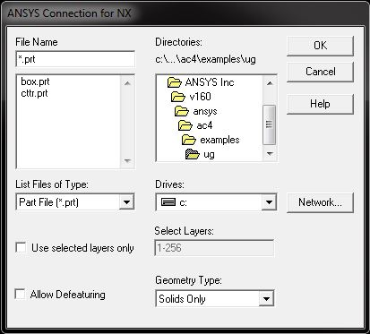
Select . The Connection for NX dialog box appears, as shown below.
Select the desired UG/NX file. In addition to the file name, file location and file type options, you can modify the following values as necessary.
- Import specific layers of the NX part by checking the Use selected layers only button and by entering the layer numbers to be imported in the field beside it. You can specify one layer (for example, 5) or a range of layers (for example, 7-20). The default is to import all layers (1-256).
Allow Defeaturing - Select this button to store the model in the solid database format so that it can be defeatured after import. The default is to store the model in neutral database format, which restricts defeaturing after import.
Geometry Type - Import the part as:
Solids Only - imported as volumes (default).
Surfaces Only - Imported as areas.
Wireframe Only - Imported as lines.
All - Import all entities; use this when the file contains multiple entity types.
Press .
Import with ~UGIN Command
You can also use the following command line method to import your NX model.
- Command Syntax
~UGIN,
Name,Extension,Path,Entity,LAYER,FMT
Troubleshooting
For general troubleshooting information, please see Troubleshooting Connection Issues, or examine Problems Specific to the Connection for NX for specific issues.
The NX-to-Mechanical APDL import produces the following two files in addition to the database file.
partname.tblpartname.attr
The partname.tbl file
is the NX-to-Mechanical APDL correspondence table file, which relates
NX item names to Mechanical APDL IDs and types.
Here is a sample NX-to-Mechanical APDL correspondence table file:
!
! *** UNIGRAPHICS-TO-ANSYS CORRESPONDENCE TABLE FILE ***

.
.
.
!     Part        : square_cube
!     Units       : Inches
!     Selected Layers   : 1-256
!     Geometry Type     : Solids Only
!
!     Translator Working Tolerance:  5.0000000E-004
!     Part system Tolerance (ref):   1.0000000E-003
!
!Object Name                      ANSYS Type                ANSYS ID
NS_SIDE_FACE                        AREA                      4
NS_PEG_FACE                         AREA                      15
The NX attribute name appears in the first column, the Mechanical APDL entity type appears in the second, and the Mechanical APDL ID appears in the third.
The partname.attr file
is the NX-to-Mechanical APDL attribute file, which lists the object
attributes that are applied in NX and that are for use in Mechanical APDL.
These attributes may be used to add mesh control information, load and boundary
condition information, or material or element property information.
Here is a sample NX-to-Mechanical APDL attribute file:
!
! *** UNIGRAPHICS-TO-ANSYS ATTRIBUTE FILE ***

.
.
.
!
!     Part        : square_cube
!     Units       : Inches
!     Selected Layers   : 1-256
!     Geometry Type     : Solids Only
!
!     Translator Working Tolerance:  5.0000000E-004
!     Part system Tolerance (ref):   1.0000000E-003
!
!Object Name                        Keyword                   Value
RMsquare_cube.prt R000000b4000      EDGE_4                  (str)  bottom edge
RMsquare_cube.prt R000000ac000      FACE_3                  (str)  face3456
NS_PEG_FACE                         PEG_FACE                (real) 1258.0000
Saving Modified Part — To save the modified part produced during the NX Connection import, please use command line '-s [SAVE_AS_LOCATION]' or set as an environment variable 'ANSCONUG_SAVE_PART_AS=[SAVE_AS_LOCATION]'. The 'SAVE_AS_LOCATION' should be the full path to the part name where the user wants to save the modified NX part.
NX and the connection for NX require a number of environment variables to run properly. One of these variables is set by the Ansys installation, and others are set by the NX installation. Because most of these environment variables are set during the installation, you will only need to reset them if you have used non-default installation directories.
Note: Both of the following variables must be set to import a part. Check to see what variables have been set for your platform, and if necessary, set these variables as indicated below.
- UGII_BASE_DIR
Sets the location of the NX files; set by the NX installation. A typical value for this variable is C:\Program Files\Siemens\NX1926.