You can control how different symbols and text entries in your graphics window appear:
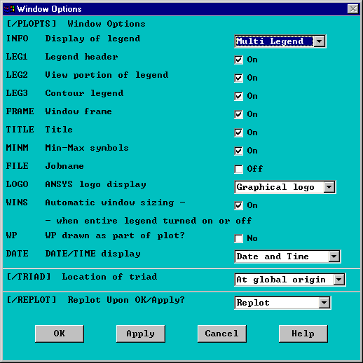
You can use legends to help define and clarify the data in your display. The Window Options Dialog Box is the "master" legend control. It controls whether or not the legend is displayed, the type of legend display, and in some cases, the content of your legend. The position of the Triad is also controlled from this dialog box. See Figure 11.2: The Window Options Dialog Box below.
The INFO pull down window provides control for the type of legend. It allows you to turn legend displays on and off, and also to access either the Auto Legend or the Multi-Legend display. The on and off settings control the display of all legend items, for all types of legends.
The Legend On and Auto legend selections control the display of the documentation column. The documentation column display places all of your legend data along the right side of the graphics window and resizes your model area appropriately. Legend On displays the documentation data at all times, while Auto Legend displays the appropriate data, only when it is applicable.
The Multi Legend provides placement options for your text and contour scales within the model area of your graphics window. The Multi Legend options are discussed below.
The default, legend setting is the user-defined "Multi-Legend." ( - /PLOPTS,INFO,3 ).
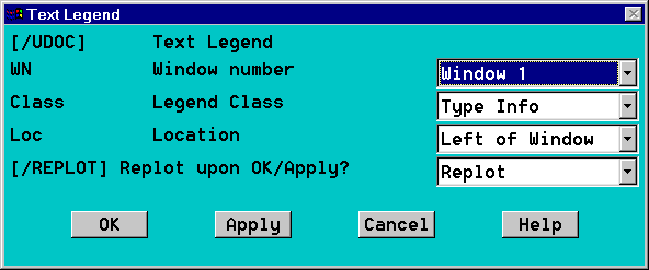
The window options dialog box shown above in Figure 11.2: The Window Options Dialog Box controls the type of legend, along with the content of the documentation column. You control the content of the Multi Legend via dialog boxes found at . The Text Legend dialog box shown in Figure 11.3: The Multi Legend Text Legend provides control of the content and placement of the various text items available for the Multi Legend option. This dialog box corresponds to the controls and priorities listed in the /UDOC command.
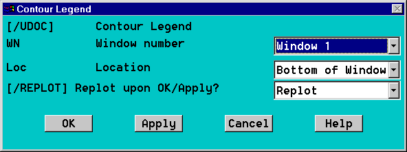
The Multi Legend setting allows you to place your contour scales along the four sides of the graphics window. You access this control via . The Contour Legend Dialog box is shown in Figure 11.4: The Multi Legend Contour Legend. This dialog box corresponds to the controls and priorities listed in the /UDOC command.
You can change the appearance of the fonts that are used to
produce the numbers and characters shown on your displays. In the GUI, select
, or issue the
/DEVICE,FONT,KEY command. This
command requires the Val1 through
Val6 arguments to specify font information.
The /TRIAD command () enables you to change the location of the global triad symbol on your display. The actual mathematical position of the global origin does not change.
Issue the /TRIAD command to display or hide the global triad.
Issue the /PSYMB command to control the local, nodal, and element coordinate system triads.
Issue the WPSTYL command to control the working plane triad.
You can display the working plane grid as a triad only, grid only, or both triad and grid. Issue the WPSTYL command to change from one style to another. There are two methods of turning the working plane on for displays:
WPSTYL with no arguments toggles the working plane grid, asterisk, and triad on and off immediately, as an overlay image on the existing display.
/PLOPTS,WP,ON specifies that the working plane be activated for subsequent displays.
In this case, the working plane is drawn as part of the display (not just an overlaid image). This method is therefore best used in combination with a hidden-line technique for viewing the location of the working plane with respect to a 3D model.
Issuing /PLOPTS,VERS,1 causes the program logo to appear in the upper right corner of the screen (along with the version number).


