This example uses the FLUID30 and SHELL181 elements in a transient analysis to calculate the hydrostatic pressure of a water container. The sloshing effect is simulated by applying a free surface (SF,,FREE) to the pressure-based acoustic elements and defining acceleration due to gravity.
The shell and acoustic elements model the container and water, respectively, with these dimensions:
| container height = 10 m |
| container radius = 5 m |
| wall thickness = 0.1 m |
| water depth = 8 m |
| Material Properties | |
| Container | Water |
| Elastic modulus = 210 GPa | Mass density = 1000 kg/m3 |
| Major Poisson's ratios = 0.3 | Speed of sound = 1500 m/s |
| Mass density = 7800 kg/m3 | |
The bottom of the container is fixed. The interfaces between the structure and the water are flagged with the fluid-structure interaction surface load (SF,,FSI).
To obtain a stable hydrostatic pressure status in a transient analysis:
The ramped gravitational acceleration must be applied during the first period, then kept constant for the rest of solution time.
The time increment must be unchanged during the entire solution.
If a transient sloshing problem is solved, other loads should be applied after the stable hydrostatic pressure status is reached.
/batch
/nopr
/prep7
z_bottom=-8    !position of the bottom
p_radius=5     !radius of the container
p_height=10    !Height of the container
p_depth=8      !depth of water
p_thick=0.01   !thickness of the container
p_nh1=8        !number of mesh in vertical direction below water surface
p_nh2=2        !number of mesh in vertical direction above water surface
p_nr=6         !number of mesh in radial and circumferential direction
z_ws=z_bottom+p_depth
z_top=z_bottom+p_height

! container material property
mp,ex,1,2e11
mp,prxy,1,0.3
mp,dens,1,7800
! water material property
mp,dens,2,1000
mp,SONC,2,1500
! define elements
et,1,shell181
et,2,fluid30,0,0
sectype,1,shell,,Sec1
secdata, p_thick,1,0.0,3
secoffset,MID
! create model
wpoffs,0,0,z_bottom
cyl4,0,0,,,p_radius,360,p_height
wpoffs,0,0,p_depth
vsbw,all
vsel,s,loc,z,z_ws,z_top
vdele,all
asel,s,loc,z,z_top
adele,all
allsel,all
! create the geometry
wprot,0,0,90
asbw,all
vsbw,all
wprot,0,90,0
asbw,all
vsbw,all
wpcsys,-1,,
lsel,s,loc,z,z_bottom
lsel,a,loc,z,z_ws
lsel,a,loc,z,z_top
lesize,all, , ,p_nr, , , , ,1
lsel,all
lsel,u,loc,z,z_bottom
lsel,u,loc,z,z_ws,z_top
lesize,all, , ,p_nh1, , , , ,1
lsel,all
lsel,u,loc,z,z_top
lsel,u,loc,z,z_bottom,z_ws
lesize,all, , ,p_nh2, , , , ,1
lsel,all
! mesh
type,1
mat,1
secnum,1
mshape,0,2d
mshkey,1
asel,s,ext
asel,a,loc,z,z_ws,z_top
asel,u,loc,z,z_ws
amesh,all
allsel,all
type,2
mat,2
mshape,0,3d
mshkey,1
vmesh,all
allsel,all
! group the fsi nodes
csys,1
nsel,s,loc,x,p_radius
nsel,a,loc,z,z_bottom
cm,n_fsi,node

nsel,s,loc,z,z_ws
cm,n_ws,node
allsel,all
! set constrains on the bottom
nsel,s,loc,z,z_bottom
d,all,ux,0
d,all,uy,0
d,all,uz,0
allsel,all
! flag fsi surface
eslv
sf,n_fsi,fsi
! flag sloshing surface
sf,n_ws,free
allsel,all
save
finish

/solu
antyp,trans
trnopt,full
! ramped gravity acceleration for first load step
kbc,0
acel,0,0,9.8
timint,on
time,5
delt,0.25
outres,all,all
solve
! keep constant gravity acceleration
time,7
kbc,0
acel,0,0,9.8
solve
! continue the constant gravity acceleration
time,9
acel,0,0,9.8
solve
finish
/com,**** analytic result *****
pres=1000*9.8*p_depth
*msg,info,pres
Pressure %g
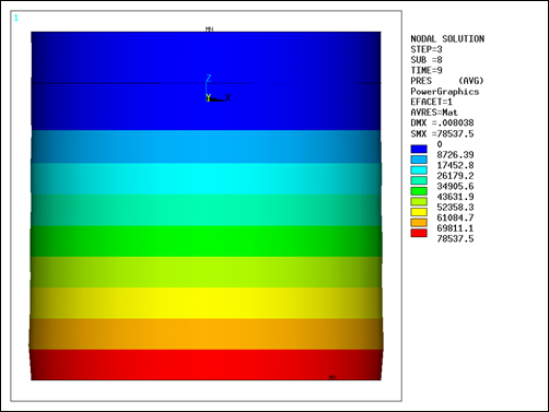
The hydrostatic pressure is given by  , where ρ is the mass density of water, g is the acceleration due
to gravity, and η is the displacement from the sloshing surface. For this example,
the maximum analytic pressure is 78400 Pa. The maximum calculated pressure is 78537 Pa
at time = 9 seconds.
, where ρ is the mass density of water, g is the acceleration due
to gravity, and η is the displacement from the sloshing surface. For this example,
the maximum analytic pressure is 78400 Pa. The maximum calculated pressure is 78537 Pa
at time = 9 seconds.