


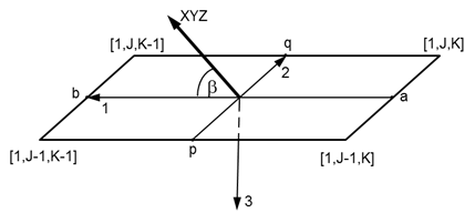
For 3D shell parts, a local co-rotational element coordinate system is used for the geometrical definition of the shell element.
The local co-rotational coordinate directions for structured shells are found as follows:
The direction 1 is a vector from the centroid of the element face K (point a) to the centroid of the element face K-1 (point b).
Next find the centroids of the faces at J and J-1, which are points p and q.
Direction 3 is the cross product of direction 1 and the vector through points p and q.
Direction 2 is the cross product of directions 1 and 3.
The local co-rotational coordinate directions for unstructured shells are found in a similar fashion as for structured shells and are shown in Figure 2.8: Co-rotational coordinate system used for 3D unstructured Shell elements:
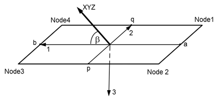
The first principal material direction is defined by a vector in XYZ space (XYZ in Figure 2.7: Co-rotational coordinate system used for 3D structured Shell elements and Figure 2.8: Co-rotational coordinate system used for 3D unstructured Shell elements) and makes an angle (𝛃) with the first co-rotational direction 1.
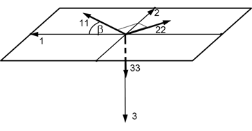
For a 3D shell element, the first material direction (11) lies in the 1-2 co-rotational coordinate plane and its direction is obtained through a rotation from the co-rotational 1 direction over an angle 𝛃 around the co-rotational 3 direction (Figure 2.9: Material directions defined in XYZ-space for 3D Shell elements).
The third material direction 33 coincides with the co-rotational direction 3. The second material direction (22) is defined in the 1-2 co-rotational coordinate plane, and is normal to the plane through the first material direction 11 and the co-rotational 3 direction.
Note: Angle 𝛃 can vary between 0° and 180°.
You are allowed to define the initial orientation of the principal material axes in one of two ways, as shown in X-Y-Z Space and I-J-K Space.