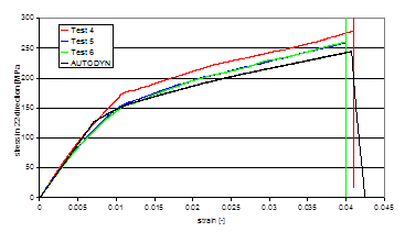
This summary describes the work carried out by the Ernst-Mach-Institute (EMI) and Century Dynamics Ltd (CDL) under ESA research contract No. 12400/97/NL/PA(SC), CCN No. 2 [2]. The aim of this project, termed ADAMMO, was to develop and further improve the composite material characterisation and modelling techniques for modelling hypervelocity impact conditions based on the study of Advanced Material Model for Hypervelocity Impact Simulations. The focus of the study was to allow better prediction of the levels of damage and residual strength in composite materials after impact. A methodology was implemented to incorporate anisotropic hardening observed in some highly nonlinear composite materials such as Kevlar-epoxy, whilst retaining the ability to couple the constitutive response to a nonlinear equation of state. Simulations of static tensile tests agreed well with experiment (see Figure 7.4: Results from Simulation of 0° Tension Test).
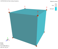
An orthotropic damage model, outlined in Orthotropic Damage Model, was implemented into Autodyn during the ADAMMO project. In short the softening behavior observed in some composite materials is modelled using a crack softening approach where damage is accumulated as a function of crack strain and the ability of a laminate to carry tensile loads is reduced.
A simulation was performed with similar loading to that experienced by the material in a short beam bending test.
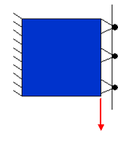
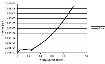
The resulting shear stress-deflection curve obtained from the simulation is shown in Figure 7.5: Simulation of Short Beam Shear Test. The response is linear elastic until the material begins to fail in shear after which a much reduced stiffness is initially observed. As the shear strain in the material continues to increase, the response hardens as the fibers re-orientate and start to pick up the shear load. This behavior is the same as that observed in the short beam bending characterisation test and demonstrates the versatility of the orthotropic model.
A number of the plate impact damage tests were simulated. In this test a symmetric assembly of Kevlar-epoxy and Al plates are used to prevent delamination caused by superposition of release waves. A schematic diagram of the test geometry is shown in Figure 7.6: Schematic Diagram of Experimental Setup.
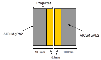
Figure 7.7: Simulation Results of 276 m/s Impact Velocity
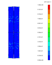 | 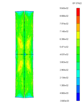 | 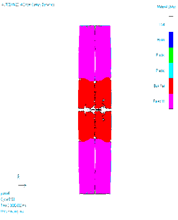 |
(a) Orthotropic damage model Through thickness damage | (b) Orthotropic damage model Through thickness plastic strain | (c) Brittle damage model (AMMHIS) |
The orthotropic damage model predicts some damage for a 276m/s velocity impact, due to hardening of the material (Figure 7.7: Simulation Results of 276 m/s Impact Velocity). This is close to the experimental result that shows limited amounts of delamination. The brittle damage model shows extensive delamination and even some bulk failure of the material which is clearly an over prediction of the levels of damage.
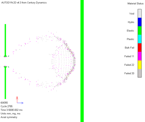
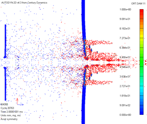
In conjunction with the hardening model described above, these additional orthotropic material models have been extensively validated by comparison with hypervelocity impact experiments. A series of debris cloud damage experiments were performed at EMI designed to generate impacted targets with damage gradients that are fully damaged in the central impact region and little damage at the extent of the targets.
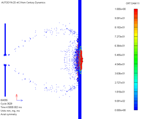
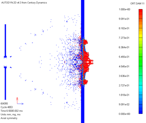
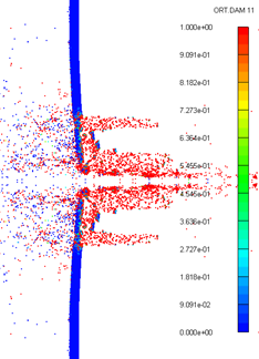
Figure 7.8: Test 4355 – Through Thickness Damage During Impact shows the simulation of test 4355 - a 8.2mm Al sphere impacting an 2.0mm Al bumper at 4.68km/s. The resulting debris cloud then impacts a 5.7mm thick Kevlar-epoxy target.
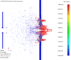
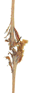
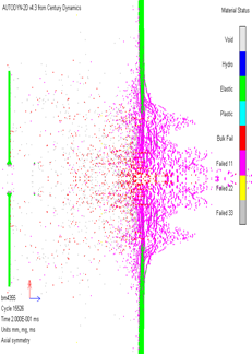
Figure 7.9: Final Damage of Test 4355 shows the final state of the simulation and the same configuration simulated without hardening included and using the brittle damage model (AMMHIS). The ADAMMO simulation produces much more compact level of damage with significant amounts of intact material remaining adjacent to the main impact zone as observed in experiment.