


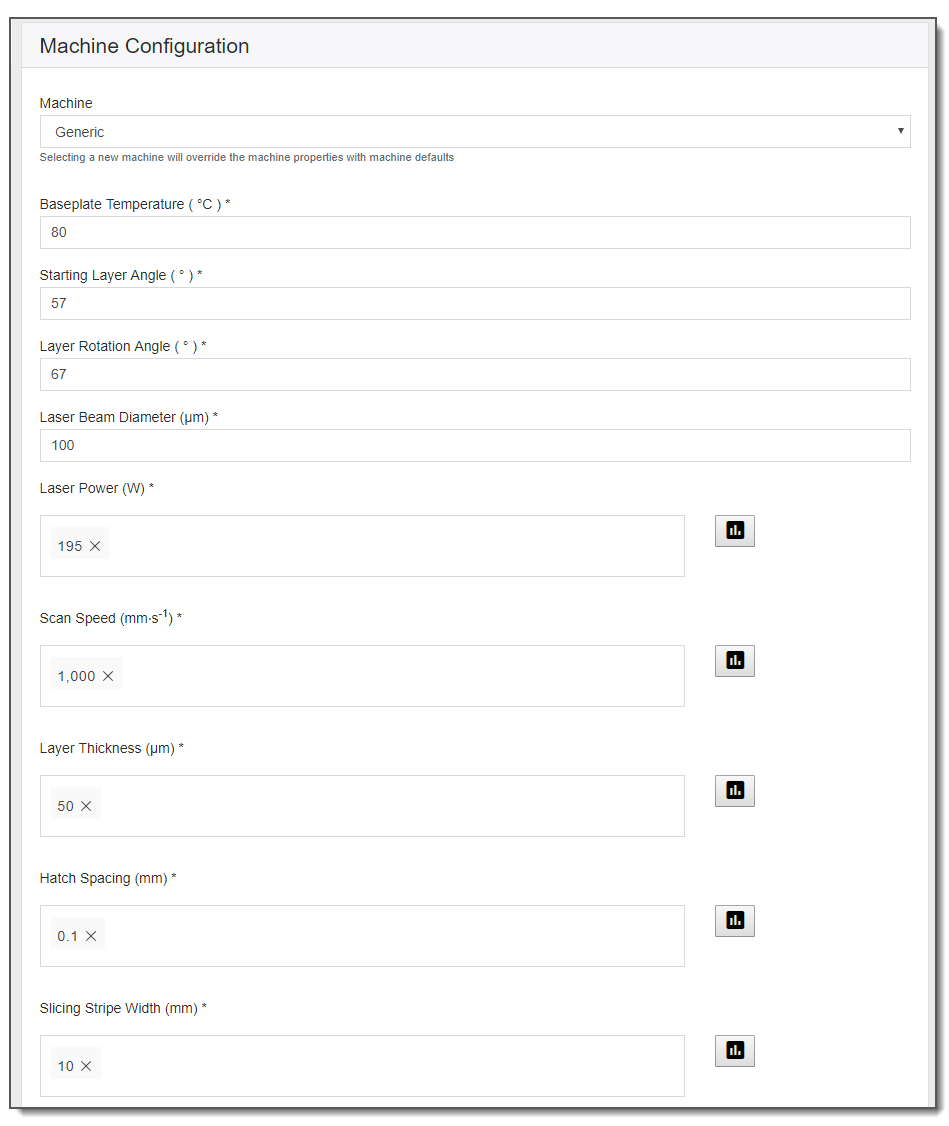
Because many build layers are simulated in porosity simulations, you need to account for your particular PBF machine and your chosen scan pattern. See Understanding Machine Parameters for descriptions of these input parameters.
![]()
For our case study, note that we cannot enter all our speeds, powers, and hatch spacings on one simulation form because that would produce a full factorial simulation of 4 powers, 5 speeds, and 5 hatch spacings for 100 total permutations. Instead, we ran 4 separate simulations, as shown here.
| Simulation A | Simulation B | Simulation C | Simulation D |
|---|---|---|---|
| Power = 150, Speed = 800 | Power = 200, Speed = 900, 1000, and 1100 | Power = 250, Speed = 1000, and 1100, and 1200 | Power = 300, Speed = 1100 |
| Hatch Spacing = 0.05 | Hatch Spacing = 0.05 | Hatch Spacing = 0.05 | Hatch Spacing = 0.05 |
| Hatch Spacing = 0.07 | Hatch Spacing = 0.07 | Hatch Spacing = 0.07 | Hatch Spacing = 0.07 |
| Hatch Spacing = 0.09 | Hatch Spacing = 0.09 | Hatch Spacing = 0.09 | Hatch Spacing = 0.09 |
| Hatch Spacing = 0.11 | Hatch Spacing = 0.11 | Hatch Spacing = 0.11 | Hatch Spacing = 0.11 |
| Hatch Spacing = 0.13 | Hatch Spacing = 0.13 | Hatch Spacing = 0.13 | Hatch Spacing = 0.13 |
| 5 permutations | 15 permutations | 15 permutations | 5 permutations |