In addition to the general support parameters, parameters specific to rod supports allow you to control:
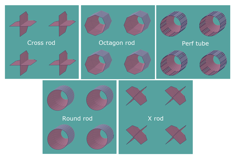
The rod shape (type), either cross rod, octagonrod, perf tube, round rod, or X rod
The rod diameter
Clearance between the part and the supports
The rod distribution, that is, the placement and spacing of rods as determined by several possible sampling techniques that each have their own settings
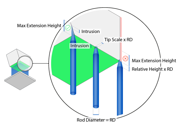
Characteristics of the tip and base of the rod, including intrusion
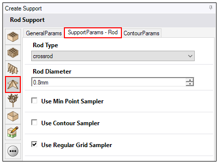
Rod Type
Rod Type: The shape, or form, of the rods for the rod support. Types are shown in the following figure.
Rod Diameter
Rod Diameter: The diameter of the individual rods, in millimeters.
Part Clearance

 Check Part Clearance: If enabled, you can define parameters for
the minimum distance between a vertical wall and supports. This avoids the collision of parts
and supports.
Check Part Clearance: If enabled, you can define parameters for
the minimum distance between a vertical wall and supports. This avoids the collision of parts
and supports.
Clearance: The minimum distance between a vertical wall of the part and the support walls, in millimeters.
Collision Volume Vertical Offset: The vertical distance from a part surface in which the part clearance function is not applied, in millimeters. This creates a fictitious wall between the part and the area in which the part clearance function is applied.
Collision Volume Inclination: The angle of the fictitious wall from which the part clearance function is not applied, in degrees.
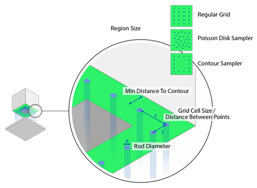
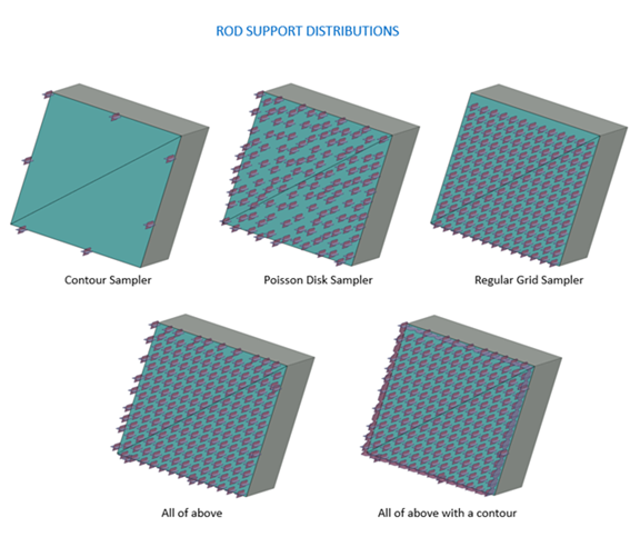
Rod Distribution
The spacing and pattern of how rods are distributed under a surface region are determined by one or more sampling selections.
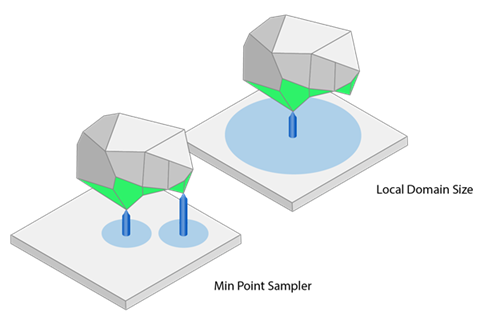
Use Min Point Sampler: If enabled, rod supports are generated
in a local minimum of a surface to be supported. This prevents geometries from being created
loose in the powder.
-
Min Distance to Outer Perimeter: The minimum distance between the rod
supports and the outer perimeter of the support region, in millimetres. (Note: This feature
applies even if a contour wall is disabled.)
-
Local Domain Size Distance: The diameter of a local minimum in which no
other minimum should be searched for, in millimeters. The diameter is shown as light blue
circles in the figures below.
Use Contour Sampler: If enabled, rod supports are generated
along the edges of the surface to be supported.
-
Min Distance to Outer Perimeter: The minimum distance between the rod
supports and the outer perimeter of the support region, in millimetres. (Note: This feature
applies even if a contour wall is disabled.)
-
Min Distance Between Points: The minimum distance between the individual
rods of the rod support, in millimeters.
Use Regular Grid Sampler: If enabled, rods for the rod support
are generated at regular intervals for the selected surface to be supported. In doing this, a
fictitious cell is created for each rod of the rod support and the size of this cell can be
changed. In this way, you can define the minimum distance between the rods.
Min Distance to Outer Perimeter: The minimum distance between the rod supports and the outer perimeter of the support region, in millimetres. (Note: This feature applies even if a contour wall is disabled.)
-
Grid Cell Size X: The width of the fictitious cell in the X-direction,
in millimeters.
-
Grid Cell Size Y: The width of the fictitious cell in the Y-direction,
in millimeters.
Use Poisson Disk Sampler: If enabled, rod supports are
generated and distributed for the surface to be supported based on a statistical Poisson distribution.
-
Min Distance to Outer Perimeter: The minimum distance between the rod
supports and the outer perimeter of the support region, in millimetres. (Note: This feature
applies even if a contour wall is disabled.)
-
Min Distance Between Points: The minimum distance between the individual
rods of the rod support, in millimeters.
-
Seed: The starting point for the random generator for the Poisson
sampling distribution. If 0, the distribution is random for each regeneration of the rod
support. If Seed is set to a specific number >0, the rod distribution is deterministic and
therefore reproducible. A negative Seed value is not valid.
Tip and Base of Rod
Tip Height: The height of the tip of the rod, in
millimeters.
Tip Scale: The scale (proportion) of the tip of the rod
relative to the rod diameter. For example, if Rod Diameter is 0.8 mm and Tip Scale is 0.5, then
the tip diameter will be 0.4 mm, which is half of the rod diameter.
Tip Intrusion: The distance the top of the support rods penetrate into the part, in millimeters. This intrusion length is not included in Tip Height, rather, it is an extra distance added above the tip height.
Tip Max Extension Height: The distance within which the tip of
the rod will attach itself to a mesh on both the inside and outside of an edge, chamfer, or
step, in millimeters. Depending on geometry, you may need to increase the Max Extension Height
to ensure attachment to a step or chamfer.
Base Height: The height of the base of the rod, in
millimeters.
Base Scale: The scale (proportion) of the base of the rod
relative to the rod diameter. For example, if Rod Diameter is 0.8 mm and Base Scale is 0.5, then
the base diameter will be 0.4 mm, which is half of the rod diameter.
Base Intrusion: The distance the bottom of the support rods penetrate into the part (for part-to-part supports), in millimeters.
Base Max Extension Height: The distance within which the base
of the rod will attach itself to a mesh on both the inside and outside of an edge, chamfer, or
step, in millimeters. Depending on geometry, you may need to increase the Max Extension Height
to ensure attachment to a step or chamfer.