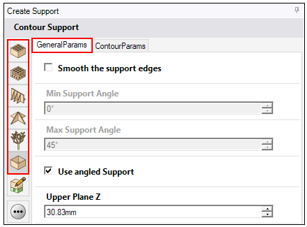
For any of the predefined support types, general parameters allow you to control:
Smoothing of edges of the support walls
Whether to force the support to build to the baseplate
Whether the supports are angled away from the part to avoid part-to-part supports
Rotation of supports relative to the gas flow direction
Smooth the Support Edges
Support regions are calculated based on the triangular facets. Every facet is examined with respect to Overhang Angle and Region Size. Therefore support regions usually have sharp edges due to triangle corners. Since supports are generated straight down from the regions, rough edges of support walls are likely. This option allows you to achieve some smoothing of the support edges.
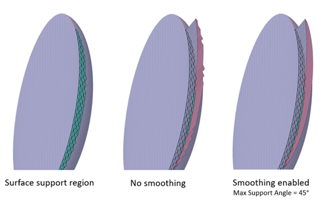
 Smooth the Support Edges. If enabled, the sharp edges of the
support structure are smoothed within the bounds of Min Support Angle and Max Support Angle. If
disabled, supports are generated based solely on support region shapes.
Smooth the Support Edges. If enabled, the sharp edges of the
support structure are smoothed within the bounds of Min Support Angle and Max Support Angle. If
disabled, supports are generated based solely on support region shapes.
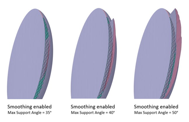
Min Support Angle: The minimum angle between the part and the baseplate up to which the supports are generated.
Max Support Angle: The maximum angle between the part and the baseplate up to which the supports are generated. This means that you can increase the distance between the smoother drawn edge and the start of the support surface and therefore reduce the area to be supported.
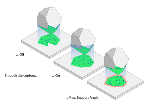
Following is the half sphere part example with a contour-only support with and without smoothed edges.
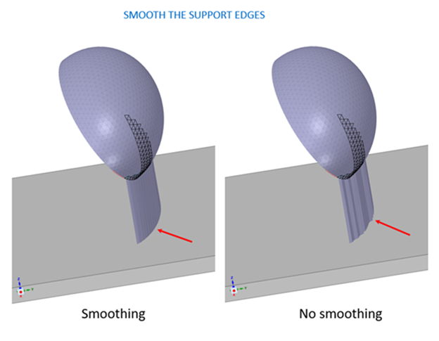
Here we've hidden the baseplate and rotated the part for better viewing of the support edges with various settings.
Force to Baseplate
 Force build support to baseplate. If enabled, supports will be
forced to build to the baseplate. We recommend you enable this option when you use angled
supports.
Force build support to baseplate. If enabled, supports will be
forced to build to the baseplate. We recommend you enable this option when you use angled
supports.
Known Limitation
Using angled supports from one surface of the part to another is currently not available, especially if the lower part surface is curved (non-flat). In such a case the part-to-part support fails to compute a valid attachment to the lower part surface. This is why we recommend enabling the Force build support to baseplate setting.
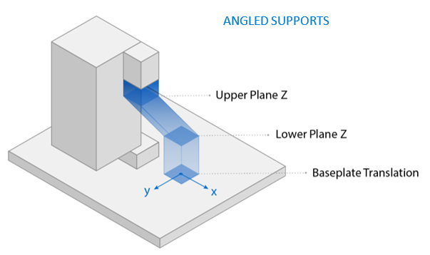
Angle the Supports to Avoid Part-to-Part Supports
Use Angled Support. If enabled, supports will be angled away
from part features using distance criteria defined by Upper Plane Z, Lower Plane Z, and
Baseplate Translation in the X and Y-directions. This is done to avoid having supports run into
lower portions of the part.
Upper Plane Z: The distance between the baseplate and the top end of the angled area of the support, in millimeters.
Lower Plane Z: The distance between the baseplate and the bottom end of the angled area of the support, in millimeters.
Baseplate Translation X: The offset of the lower area of the support relative to the upper area of the support in the X-direction, in millimeters.
Baseplate Translation Y: The offset of the lower area of the support relative to the upper area of the support in the Y-direction, in millimeters.
The supports will not be angled if the Baseplate Translation values are both zero, regardless of the values of Upper Plane Z and Lower Plane Z.
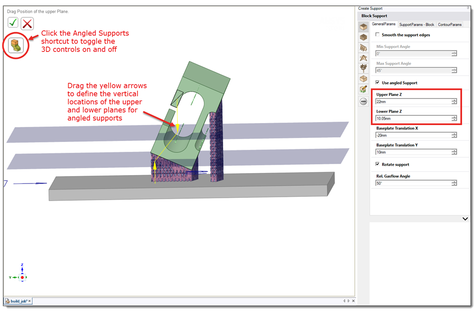
Angled Supports Shortcut
For all support types that allow angled supports, there is a convenient shortcut tool that allows you to drag guide planes up and down to define the Upper Plane Z and Lower Plane Z parameters. Dragging the planes in 3D view automatically adjusts the corresponding input fields. Also, toggling on the shortcut button automatically enables the Use Angled Support check box.
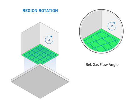
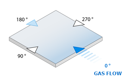
Rotate Supports Relative to the Gas Flow Direction
Rotate Support. If enabled, supports will be aligned relative
to the gas flow direction according to Rel. Gas Flow Angle.
Rel. Gas Flow Angle: The angle for the rotation of the supports, in degrees. An angle of 0° means that the supports are aligned in the direction of the gas flow.