


In addition to the general support parameters, parameters specific to adaptive cell supports allow you to control:
The adaptive cell shape (type); either default, cross attachment, or full attachment
The size and number of subdivisions of the cells
Whether the supports extend over the border of the part
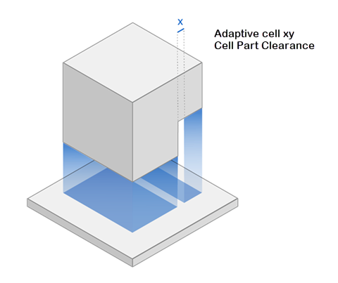
Clearance between the part and the supports
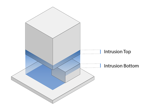
How far the supports intrude into the part
Tooth-shaped cutouts at the upper edges of supports
Whether to force part-to-part supports
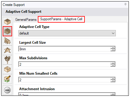
Adaptive Cell Type
Adaptive Cell Type: The shape of the adaptive cell supports at the top of the support walls near the attachments. Types include:
Default: Cross-rods will be built at each intersection of cell walls.
Cross Attachment: Cross-rods will be built at each intersection of cell walls, except the middle.
Full Attachment: The walls of the uppermost cell will be extended into the part, according to the attachment intrusion parameter.
The following options and defaults are the same for all adaptive cell types.
Size and Subdivisions of Cells
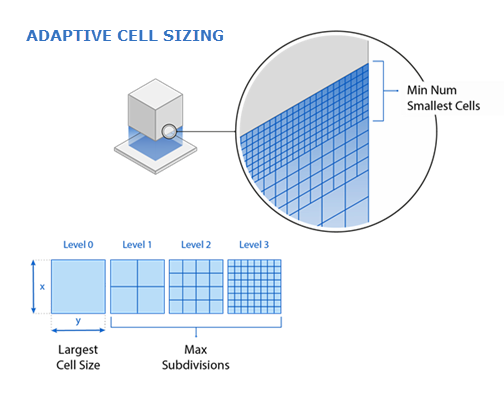
Largest Cell Size: The largest cell size (the lowest level shown in the figure), in millimeters.
Max Subdivisions: A number defining how frequently the horizontal adaptive cell cells may be reduced in size. For example, a value of 3 will generate a maximum total of four levels as shown in the figure.
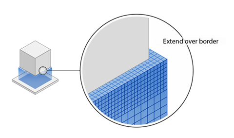
Extend Over the Border

 Extend Over Border: If enabled, the supports in the X and
Y-direction may extend past the edge of the support surface. This means that the supports may be
wider than the part in some cases.
Extend Over Border: If enabled, the supports in the X and
Y-direction may extend past the edge of the support surface. This means that the supports may be
wider than the part in some cases.
Max Subdivisions Border: The maximum number of reductions in adaptive cells in the area of the contour for the support.
Min Subdivisions Border: The minimum number of reductions in adaptive cells in the area of the contour for the support.
Smallest Cell Inwards: The depth of the adaptive cells (based on the values under Max Subdivisions Border and Min Subdivisions Border), in millimeters.
Check Part Clearance
Smallest Cells for Clearance: The size of the smallest adaptive cells for clearance from a vertical wall of a part, in millimeters.
Number of Smallest Cells
Min Number Smallest Cells: The minimum number of smallest adaptive cells in the vertical direction.
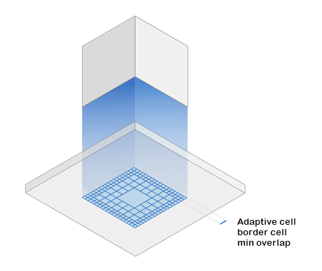
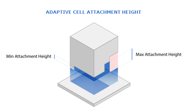
Attachments
Because only complete adaptive cells are generated, gaps may occur between the supports and the part. Attachments are used to close any gaps.
Attachment Intrusion: The distance the attachments penetrate into the part, in millimeters.
Min Attachment Height: The minimum length of attachments, in millimeters.
Max Attachment Height: The maximum length of attachments, in millimeters.
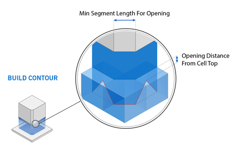
Build a Contour Around Support
Build contour: If enabled, the adaptive cell support walls are reinforced with a contour on the outermost perimeter
of the support surface.
Top Intrusion (contour): The distance the top of the contour support wall
penetrates into the part, in millimeters.
Min Segment Length for Opening (contour): The minimum length of an adaptive cell from which a contour is generated from this
adaptive cell, in millimeters.
Opening Distance from Cell Top (contour): The distance between the
uppermost end of the contour and the upper end of an adaptive
cell, in millimeters.
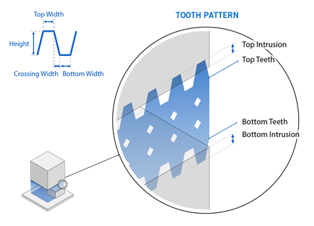
Create Top Tooth Pattern (contour): If enabled, cut-outs are
generated at the upper edge of the support in the form of teeth. The cutouts are generated
only in the contour and not in the support itself for adaptive cell supports.
Bottom Width: The lower width of each tooth, in millimeters.
Crossing Width: The distance between the end of the top width and the start of the lower width, in millimeters. This affects the distance between teeth.
Top Width: The upper width of each tooth, in millimeters. A value of zero will produce a pointed tooth at the top, subject to intrusion settings.
Height : The height of the top tooth, in millimeters.
Part-to-Part Support
Do part-to-part support: If enabled, supports can also be
generated between part areas as well as between the part and the baseplate.