


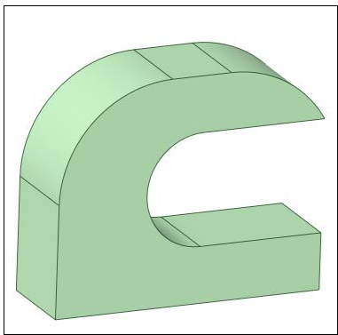
Simulations in Mechanical and Additive Print accurately predict part distortion during the build. You can use the Distortion Compensation add-in in SpaceClaim to automatically create a distortion compensated geometry, essentially reversing distortion effects. Engineers can then use the compensated geometry file in their production builds and be assured of a final part that conforms to design intent.
Note: The Distortion Compensation Add-on in Mechanical and the Distortion Compensation Add-in (beta) in SpaceClaim, described here, differ in their ease of use and flexibility. The add-on in Mechanical automates the compensation process from beginning to end by faceting and compensating the geometry then re-running iterations until the final geometry falls within defined tolerances. The add-in in SpaceClaim involves a much more manual process, but enables greater control of the remeshed triangles and mapping of the solution results that may enable you to handle more complex situations.
The following topics are covered:
First be sure the Distortion Compensation (Beta) add-in is enabled in SpaceClaim:
File>SpaceClaim Options>Add-ins
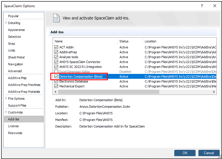
Once the add-in is enabled, you will need to close and reopen SpaceClaim. This is only necessary the first time this option is enabled.
In Mechanical, set up and solve an additive simulation, as normal, using either an LPBF Inherent Strain or an LPBF Thermal-Structural system.
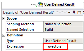
Create the UVECTORS result item
Insert a user defined result and write the expression “UVECTORS.”
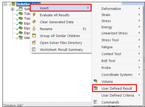
Right-click Solution and evaluate all results.
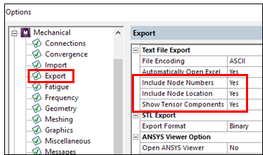
Turn on node locations for exported data
Go to File > Options > Export and make sure to include the node numbers, node locations and tensor components.
Export the UVECTORS result in a .txt file
Right-click the UVECTORS result, Export > Export Text File
Open SpaceClaim and load geometry used in simulation.
Go to Distortion Compensation tab
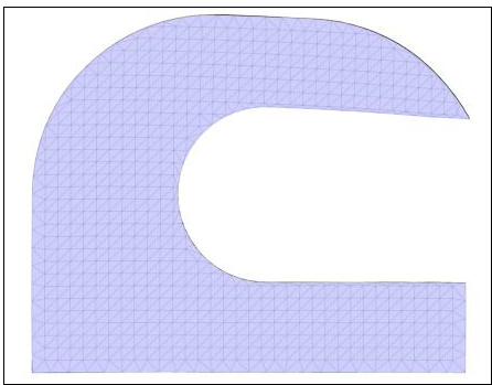
Convert geometry to facets if not already faceted. In this step, we can control the quality of the faceted geometry to prevent the need for future adjustments.
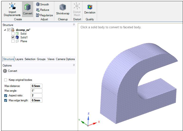
Clean up geometry if needed with Smooth, Reduce, Regularize, and Shrinkwrap tools.
Import distortions
Click Import Displacements button, select the exported UVECTORS result.
You can also import a .vtk file if you have one.
Distort Mesh and input the scale factor.
Compare geometries with the Deviation tool. Deviation probes can help to visualize areas with large distortion.