


Topology optimization is an exciting technology that allows designers to optimize material layout within a given design space, and for a given set of loads, boundary conditions and constraints, with a goal of maximizing the performance of a product. The optimal shape of a part is often organic and counterintuitive, and difficult or impossible to manufacture using traditional methods. By its very nature, additive manufacturing opens up whole new possibilities for the real-world production of these optimized parts. Along with the potential gains comes challenges unique to the manufacturing process, however. We've seen that the use of supports for overhanging features during the printing process is necessary but costly. If we could optimize our product designs while minimizing the requirement for supports at the same time, we will be taking advantage of the best of both technologies.
The AM Overhang Constraint available in Ansys Mechanical's topology optimization tools allows us to do just that. The goal of the overhang constraint is to create a self-supporting structure so that it may be printed without adding supports. We will examine the overall workflow of using topology optimization combined with AM Process Simulation as well as the specific usage of the overhang constraint in this section. For a general discussion of how topology optimization is implemented in Ansys Mechanical, see Structural Optimization Overview.
Topology Optimization and AM Process Simulation Workflow
The general workflow in a linked topology optimization and AM simulation is shown in the following figure.
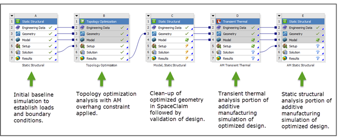
Step A – Run an initial static structural analysis to establish loads and boundary conditions and baseline results in Mechanical.
Step B – Run the topology optimization analysis with the AM Overhang Constraint in Mechanical.
Highlight Topology Optimization, right-click and select Insert > AM Overhang Constraint. In Details, change Build Direction and Overhang Angle to your desired values.
Parts designed using the AM Overhang Constraint are constrained more and results will include more material than those optimized without the constraint. To allow more flexibility in solving this highly nonlinear problem, we recommend you specify a range for the response constraint rather than just a constant value. For example, if you want to reduce the mass in your part by 70%, we recommend you allow the program to use a Percent to Retain range between 25 and 30% for maximum flexibility in the algorithm. Defining a range for response constraint in combination with overhang constraint will frequently require fewer iterations.
Under Topology Optimization, select Response Constraint. In Details, under Definition, choose Mass or Volume for Response. Change Define By to Range and enter a range of values for Percent to Retain Min and Max.
Step C – Clean up the optimized geometry in SpaceClaim and then validate the design in Mechanical. Search for the Additive Manufacturing section in the SpaceClaim documentation. Also, see Performing Design Validation in the Structural Optimization in Mechanical.
Steps D and E – Run the additive manufacturing simulation on the optimized design in Mechanical.
AM Overhang Constraint Methodology
The AM Overhang Constraint is defined by a printing direction and an overhang angle. The printing direction can be one of the global coordinate system axes (either the positive or negative direction).
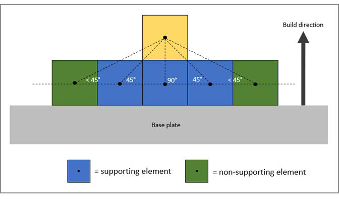
The overhang angle restricts the state of optimized elements. (Optimized elements are those that are "kept" in the final design and that contribute to the system's overall stiffness matrix; that is, are filled with material.) An element will be kept only if there is a supporting element in the layer below (or above depending on the printing direction) that is also filled with material. An element is called a supporting element of another element if the angle between the line defined by their centroids and the base plate is greater than, or equal to, the overhang angle. The following figure demonstrates the restriction with an overhang angle of 45° in 2D. The printing direction is from the bottom to the top. In order to fill the yellow element with material, at least one of the blue elements has to be filled, too. Which of the blue elements will be kept depends on the state of the surrounding elements as well as the load path. In the final design all remaining optimized elements have supporting elements.
Base Plate
The surface of the base plate is a plane perpendicular to the build direction. The base plate touches the design region from below for positive printing direction (or from above for negative ones). For a design to be printable, it requires a connection to the base plate. The results will depend on the size of the area of contact. Results of the optimization will improve with increased contact area.
Excluded Elements
Excluded elements in the design region can lead to designs that do not satisfy the overhang constraint. It cannot be guaranteed that these excluded elements are supported with respect to the overhang angle. Excluded elements are always considered to provide support to optimized elements.
Example of AM Overhang Constraint Used in Topology Optimization
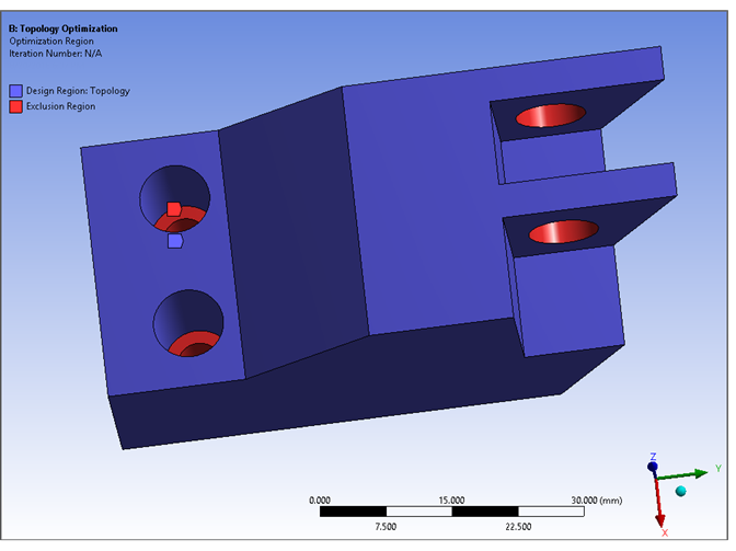
As shown in the following figure, a bracket-type component has two counterbored bolt holes at one end and a through hole going through two flanges at the other. The bolt holes are fixed and a remote force is applied to the two holes of the flanges. These regions are excluded from the topology optimization and are shown in red. The remainder of the geometry is our design region (purple). We want to minimize material on the component while still maintaining its ability to structurally support the loads.
We used topology optimization first without, and then with, the AM Overhang Constraint. We set a mass response constraint range of 10-13% material to retain. When using the AM Overhang Constraint, we set an overhang angle of 45°. The print (or build) direction is from 0 along the positive Z axis.
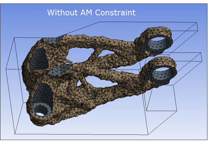
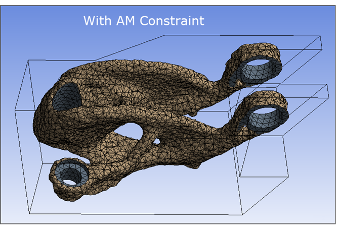
Comparing the two models, you can see there are several surfaces that will require supports in the first image, especially underneath the branched structures. While not entirely eliminating them, the second model minimizes these surfaces. Note also that the through holes will need to be supported during 3D printing. The hole surfaces were not modified, as they were excluded regions.