The IronPython script for the extension GeometryFeature is
named main.py. This section describes the functions associated
with the callbacks <ongenerate> and
<onaftergenerate>.
import units
import math

def createMyFeature(feature):
    ExtAPI.CreateFeature("MyFeature")

def vectorProduct(v1, v2):
    return [v1[1]*v2[2]-v1[2]*v2[1], -v1[0]*v2[2]+v1[2]*v2[0], v1[0]*v2[1]-v1[1]*v2[0]]

def scalarProduct(v1, v2):
    return v1[0]*v2[0]+v1[1]*v2[1]+v1[2]*v2[2]

def norm(v):
    return math.sqrt(scalarProduct(v,v))

def generateMyFeature(feature,function):

    length = feature.Properties["Length"].Value
    length = units.ConvertUnit(length, ExtAPI.DataModel.CurrentUnitFromQuantityName("Length"), "m")
    faces = feature.Properties["Face"].Value.Entities
    bodies = []
    builder = ExtAPI.DataModel.GeometryBuilder

    for face in faces:
        centroid = face.Centroid
        uv = face.ParamAtPoint(centroid)
        normal = face.NormalAtParam(uv[0], uv[1])
        radius = math.sqrt(face.Area/(math.pi*2))

        xdir = [1., 0., 0.]
        vector = vectorProduct(xdir, normal)
        if norm(vector)<1.e-12:
            xdir = [0., 1., 1.]
        s = scalarProduct(xdir, normal)
        xdir = [xdir[0]-s*normal[0],xdir[1]-s*normal[1],xdir[2]-s*normal[2]]
        n = norm(xdir)
        xdir[0] /= n
        xdir[1] /= n
        xdir[2] /= n

        arc_generator = builder.Primitives.Wire.CreateArc(radius, centroid, xdir, normal)
        arc_generated = arc_generator.Generate()

        disc_generator = builder.Operations.Tools.WireToSheetBody(arc_generated)

        normal[0] *= -1
        normal[1] *= -1
        normal[2] *= -1
        extrude = builder.Operations.CreateExtrudeOperation(normal,length)
        cylinder_generator = extrude.ApplyTo(disc_generator)[0]

        bodies.Add(cylinder_generator)

    feature.Bodies = bodies
    feature.MaterialType = MaterialTypeEnum.Add
    return True

def afterGenerateMyFeature(feature):
    edges = []
    minimum_volume = System.Double.MaxValue
    for body in feature.Bodies:
        body_volume = 0
        if str(body.BodyType) == "GeoBodySolid":
            body_volume = body.Volume
            if body_volume <= minimum_volume:
                minimum_volume = body_volume

        for edge in body.Edges:
            edges.Add(edge)
        else:
            ExtAPI.Log.WriteMessage("Part: "+body.Name)

    feature.Properties["Minimum Volume"].Value = minimum_volume

    ExtAPI.SelectionManager.NewSelection(edges)
    named_selection = ExtAPI.DataModel.FeatureManager.CreateNamedSelection()
    ExtAPI.SelectionManager.ClearSelection()
Descriptions follow of the functions associated with the callback
<ongenerate>.
The function
createMyFeature(feature)creates the geometry in the DesignModeler. It is displayed as My Feature in the Tree Outline pane.The mathematical functions
vectorProductandscalarProductare used later in the functiongenerateMyFeature.
The first several functions configure information that is used later in the creation of the geometry.
In this example, the function generateMyFeature is
referenced in GeometryFeature.xml by the callback
<ongenerate>. When invoked, it generates the
geometry feature. Within this function, the following information about the
geometry is defined:
The property
length, which is used later to create the primitive. The conversion of the length unit ensures that you are working with the expected metric unit.The scoped property
face, which in this example is three faces.The list
bodies, where the geometric features to create are added.The
builder, which serves as the ACT gateway in DesignModeler. All features and operations are accessed from here.The variable
faces, which is used as the argument to create the circle. Under faces:Define the
centroidof the scoped face.Evaluate the
normalto this face.Evaluate the
radiusthat is to be used for the arc wire.
Calculate the
xdir, which is the principle direction of the arc wire that is defined later and that is required to draw the arc.The objects
vectorProductandscalarProduct, which specify the location of the geometry’s primitives and operations.The next several objects generate an arc wire.
With the object
arc_generator, the extension uses the primitive generatorbuilder.Primitives.Wire.CreateArc. The methodCreateArc()uses arguments from faces to draw the circle. This generator can be used one or more times to build the primitive body.With the object
arc_generated, the extension uses the methodGenerate()to generate the primitive body.With the object
disc_generator, the extension uses the operations generatorbuilder.Operations.Tools.WireToSheetBodyto define a disc based on the circle.
The next several lines extrude the disc into a cylinder.
With the object
extrude, the extension uses the operations generatorbuilder.Operations.CreateExtrudeOperationto specify that the resulting extrusion is equal to the value of the propertyLength.With the object
cylinder_generator, the extension uses the methodApplyToto define the geometry to which the extrude operation is applied. This method returns a list of bodies to which the operation is applied.
Bodies added to the list
feature.Bodiesare added to DesignModeler after the generation. All other bodies used in the generation process are lost.The list
feature.Bodiescan contain both bodies and parts. You can create a part with the commandbuilder.Operations.Tools.CreatePart(list_of_bodies).The list
material.Typeallows you to enter different properties such asFreeze,Cut, andAdd. The following figure illustrates the resulting geometry given selection of the different properties. You can see the effect of different material type properties on the geometry.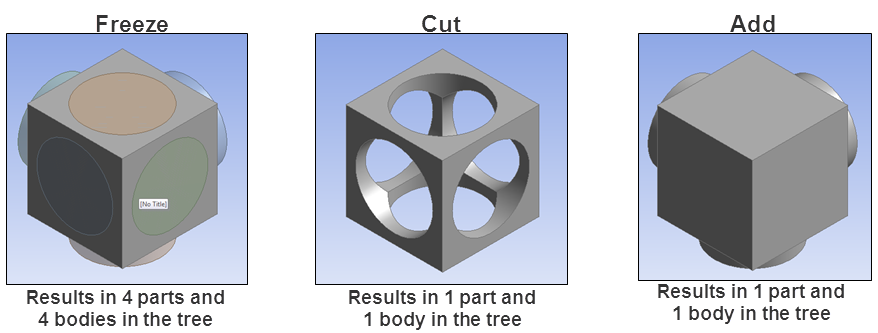
A description follows of the IronPython function associated with the callback
<onaftergenerate>. This callback specifies the
function that is invoked when the callback
<ongenerate> is complete.
The callback
<onaftergenerate>allows you to access and work with the part or bodies created previously by the callback<ongenerate>.For example, you can use it rename a part or body, suppress it, create a named selection, create a new selection via the Selection Manager, or access one or more of the geometric features of a body as its area.
Unlike the callback
<ongenerate>, which expects a return value ofTrueorFalse, the callback<onaftergenerate>does not expect a return value.The callback
<onaftergenerate>allows you to define properties for the feature to be created.
In this example, the function afterGenerateMyFeature is
referenced in GeometryFeature.xml by the callback
<ongenerate>. It accepts only the feature
itself as an argument. When called, it specifies the properties and attributes
of the feature and selects edges of the bodies created: Within this function,
the following information is defined:
The list
edges, where you add all edges of the bodies to create for the feature.The property
Minimum Volume, which in this example is the volume of the body with the smallest volume of all the bodies created for the feature. The attributecontrolis set tofloat. The attributeunitis set toVolume. Because this property has the special attributereadonlyaftergenerateset totrue, the value becomes non-editable after generation of the feature.The variable
edge, which is used to find the edges of all the bodies created for the feature.The entry
feature.Properties[Minimum
                                    Volume"].Value
sets the property Minimum Volume in DesignModeler to the valueminimum_volume.The command
ExtAPI.SelectionManager.NewSelection(edges)creates a new selection, which includes all edges previously selected.The command
named_selection =
                                    ExtAPI.DataModel.FeatureManager.CreateNamedSelection()
creates a named selection that is defined by the current selection containing all edges previously selected.
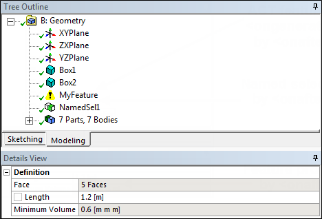
The following figures shows the feature, named selection, and properties in DesignModeler.