


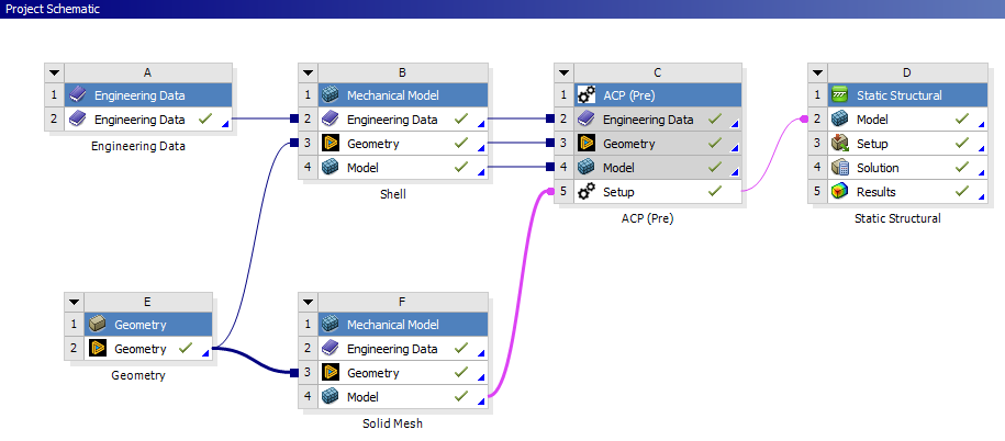
The entire geometry is prepared in SpaceClaim (system E) and contains both the shell reference surface and the solid. Therefore, the geometry is split into two parts in the subsequent workflow. The shell surface is used to specify the Composite Definitions in ACP (Pre) and is passed to system B and later to ACP (Pre), system C. The volume of the spring is required to generate the solid mesh in Ansys Mechanical and is passed to another Mechanical model (system F).
To achieve an accurate FE model of the solid with the correct material assignments, the solid geometry is split into two bodies: the Tube and the Roving. This ensures that, later, the reinforcement plies and UD roving can be mapped accurately onto their intended region and that the volume contents of the materials are correct. These bodies are passed to ACP (Pre) (the connection between system F and C) as Named Selections. The figure below shows the geometry with the two solid bodies and the Named Selections.
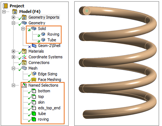
Also, other Named Selections are added which will be used to apply the boundary conditions in analysis system D. It is important that all geometries except the solid are suppressed in system F so that the data transfer from F4 (the Mechanical model) to C5 (ACP (Pre)) contains only the solid mesh.