


During the Variable Material Data workflow, you can define the variation of the scalar variables controlling the local state of the material properties over the finite element model using Field Definition objects. You can scope Field Definition objects to Element Sets, Oriented Selection Sets, and Modeling Plies.
If your field definition is based on Elements Sets or Oriented Selection Sets, all of the layers within your scoping are affected. When scoping to Modeling Plies, only the associated Analysis Plies are affected. Therefore, it is possible implement both a “layer-wise” as well as a “element-wise” application of field definitions in your finite element model. Parts of the finite element model not covered by Field Definition Objects assume default values of the field variables.
In order to understand the effect of a Field Definition Object, contour plots of the field variables are available Field Definition Plot topic of the Lay-Up Plots section.
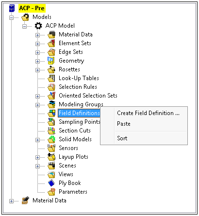
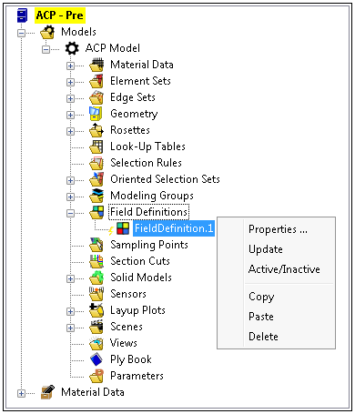
As illustrated below, once you create a Field Definition object, you use the context menu to define its features. Menu options include:
: Display the properties window of the selected Field Definition.
: Update the selected Field Definition.
: Toggle field definition object active or inactive
: Copy the selected Field Definition to the clipboard.
: Paste a table Field Definition from the clipboard.
: Delete the selected Field Definition.
Field Definition Object Properties
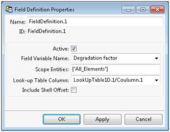
Field Definition objects can be used for element-wise and layer-wise specification of the variation of a scalar variable controlling Variable Material Data on subparts of your finite element model. You can scope layer-wise specifications to specific Modeling Plies. The properties dialog is illustrated below. Properties include:
: Name of the Field Definition. This field is initially populated with an default name.
: This selection indicates that the application processes the Field Definitions during your analysis. Inactive definitions are ignored.
: This drop-down menu provides a list of available Field Variables as defined in the Engineering Data Workspace. Note that the Temperature and Shear Angle field variables are not available for Field Definitions. Temperature is defined externally to ACP, and the Shear Angle is defined via draping calculations.
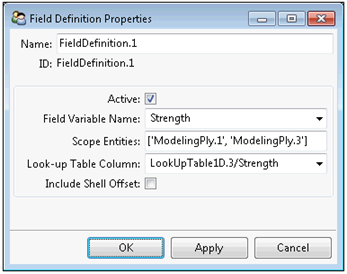
: Entry field to define the applicable element-wise field definitions. You can use a combination of Element Sets and Oriented Selection Sets in order to scope the definition to subparts of your model. For layer-wise field definitions, you can use a combination of Modeling Plies to scope the definition to subparts of your model; the Field Definition will only be applied to Analysis Plies attached to the Modeling Plies.
: Select the scalar Look-Up Table column from which the state of the field variable is interpolated from.
: Specify whether or not to include the shell offset of each analysis ply for the interpolation process. The default is to interpolate the state of the field variables at the shell element centroid. For solid elements, the actual position of each analysis ply is automatically considered and this behavior cannot be changed.
Figure 2.102: Field Definition Object Properties
| Element-Wise Field Definition | Layer-Wise Field Definition |
|---|---|
 |
 |