


There are several different Puck Failure criteria, the following sections describe them.
The two oldest Puck failure criterion formulations are simple Puck and modified Puck. Both criteria consider failure due to longitudinal loads and matrix failure mode due to transverse and shear loads separately ([ 27 ] and [ 28 ]).
For both the simple and modified Puck criteria, failure in fiber direction is calculated the same way as in the maximum stress criterion:
 | (5–60) |
Matrix failure is calculated differently for each formulation as illustrated in Equation 5–61 for simple Puck. Equation 5–62 demonstrates how tensile or compressive failure stresses are used depending on the stress state.
 | (5–61) |
where:
 | (5–62) |
The modified Puck criterion differs from the simple criterion only in the formulation for matrix failure:
 | (5–63) |
As in Hashin Failure Criterion, the failure occurs
when either  or
or  reaches one, so the failure criterion function
is:
reaches one, so the failure criterion function
is:
 | (5–64) |
Despite being called simple in the failure criteria configuration in the Failure Criteria Definition dialog the Puck modified version is actually implemented. The name is referring to the simplicity of that criterion in comparison to Puck's Action Plane Strength Criterion.
The following sections describe the different failure modes for Puck’s action plane strength criterion.
As in the simple Puck criterion, one option for evaluating fiber failure is to use the maximum stress criterion for that case ([ 29 ], [ 30 ], and [ 31 ]):
 | (5–65) |
and similarly a maximum strain criterion:
 | (5–66) |
A more complicated version for FF criterion was presented by Puck for the World Wide Failure Exercise, but the maximum stress criterion is considered sufficient for the case of FF.
Interfiber failure is formulated differently depending on the model type.
Interfiber failure, or interfiber fracture ([
29
] and [
30
]) can be explained in the cutting plane for which the
principal stress  of a UD layer is zero in the case
of plane stress.
of a UD layer is zero in the case
of plane stress.
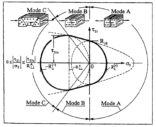
The  curve consists of two ellipses (modes
  and
and  ) and one
parabola (mode
) and one
parabola (mode  ). Generally Puck's action plane
strength criterion is formed utilizing the following 7 parameters,
). Generally Puck's action plane
strength criterion is formed utilizing the following 7 parameters,  , where
  stands for fracture
resistances and
stands for fracture
resistances and  for slope parameters of the fracture
curves. The symbols
for slope parameters of the fracture
curves. The symbols  and
and  denote the
reference to direction parallel to the fibers and transverse (perpendicular)
to the fibers. The values for
denote the
reference to direction parallel to the fibers and transverse (perpendicular)
to the fibers. The values for  and
and  define the intersections of the curve with
  -axis,
as well as
-axis,
as well as  for the intersection with
  -axis.
The slope parameters
-axis.
The slope parameters  and
and  are the inclinations in the latter intersections.
The failure conditions for IFF are:
 | (5–67) |
The superscript  denotes that the fracture resistance
belongs to the action plane.
denotes that the fracture resistance
belongs to the action plane.
 | (5–68) |
The assumption  is valid here
and leads to:
is valid here
and leads to:
 | (5–69) |
Equation 5–70 is also valid.
 | (5–70) |
As the failure criterion functions and the functions for their
corresponding stress exposure factors  are the same, they can
be written as follows (given Equation 5–69 and Equation 5–70):
are the same, they can
be written as follows (given Equation 5–69 and Equation 5–70):
 | (5–71) |
While the latter formulations have been a reduced case working in ( )-stress space, the 3D stress state can be described with Equation 5–72:
 | (5–72) |
where:

|

|

|
From the above equations, the failure criterion function is
formulated in the fracture (action) plane using the corresponding
stresses and strains. The formulations for the stresses  ,
,  , and
, and  in an arbitrary
plane with the inclination angle
in an arbitrary
plane with the inclination angle  are:
are:
 | (5–73) |
To find the stress exposure factor  the angle
  is
iterated to find the global maximum, as the failure will occur for
that angle. An analytical solution for the fracture angle is only
available for plane stress-state by assuming:
is
iterated to find the global maximum, as the failure will occur for
that angle. An analytical solution for the fracture angle is only
available for plane stress-state by assuming:
 | (5–74) |
which leads to formulations for the exposure factor:
 | (5–75) |
Puck illustrated in [
29
] that the latter criterion can be used as a criterion to determine
delamination, if an additional weakening factor for the interface  is applied, finally
resulting in:
is applied, finally
resulting in:
 | (5–76) |
The active failure mode depends on the fraction angle  and
the sign of
and
the sign of  . Delamination can occur if
  is
positive and
is
positive and  is 90 degree. The failure modes
  and
and  happen
with negative
happen
with negative  .
.
Different default values for the coefficients are set for carbon and glass fiber plies to:
Carbon: 
|
Glass: 
|
Those values are compliant with recommendations given in [ 32 ].
To take into account that some fibers might break already under
uniaxial loads much lower than loads which cause ultimate failure
(which can be seen as a kind of degradation), weakening factors  can be introduced
for the strength parameters. Puck formulated a power law relation
in [
29
]:
can be introduced
for the strength parameters. Puck formulated a power law relation
in [
29
]:
 | (5–77) |
where  and
and  and
and  can be can
be experimentally determined.
can be can
be experimentally determined.
Different approaches exist to handle this problem numerically. The function given in Equation 5–77 can be replaced by an elliptic function:
 | (5–78) |
where:

|
 and and  are degradation
parameters. are degradation
parameters. |
In ACP, the stress exposure factor is calculated by intersecting the weakening factor ellipse with a straight line defined by the stress vector using the parameters:

|

|

|

|
Otherwise the fiber failure criterion determines the stress
exposure factor  .
.
Default values for the degradation parameters are  and
and  .
.