In this section, you will create a composite model with two Modeling Plies, import the geometries to define the Cut-Off Selection Rule and the Snap-To geometry, then extrude the composite model into a solid structure and smooth its surface.
Follow these steps to create the first ply:
In the Tree View, right-click Modeling Groups and select Create Modeling Group (A, below). Change the Group's Name to
PlyGroup.1(B), click Apply (C), then close the dialog.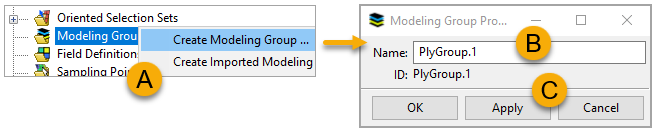
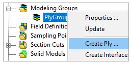
Under Modeling Groups, right-click PlyGroup.1 and select Create Ply.
In the Modeling Ply Properties dialog, place the cursor in the Oriented Selection Sets field (A, below), then select OrientedSelectionSet.1 under Oriented Selection Sets in the Tree View. Choose Epoxy_Carbon_UD_230GPa_Prepreg_0.5mm from the Ply Material drop-down menu (B).
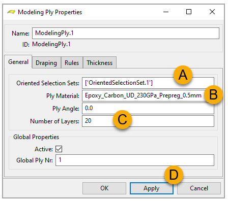
Enter
20in the Number of Layers field (C, above). Click Apply (D), then close the dialog.In the Tree View, expand Section Cuts. Right-click the predefined SectionCut.1 and select Update to view the layers of PlyGroup.1.

Close ACP and go back to Workbench.
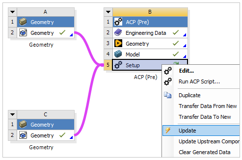
In this section, you will import two CAD geometries into ACP.
In Workbench, click from Component Systems in the Toolbox, then drop it into the Project Schematic pane.
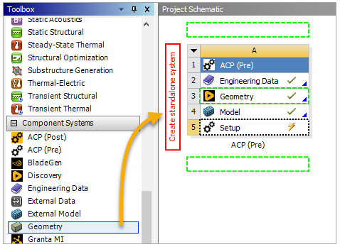
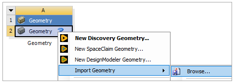
Right-click Geometry, select Import Geometry, then select Browse. Choose the CUT_OFF_GEOMETRY.stp in the project folder.
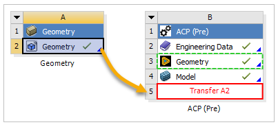
Click the A2 Geometry cell then drop it onto the B5 Setup cell to connect the two cells.
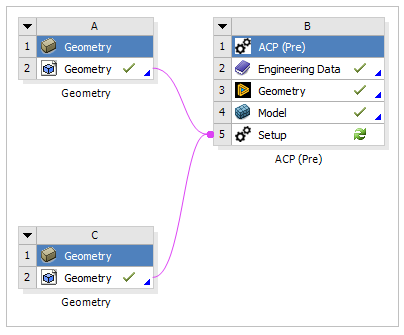
Follow steps 1 to 3 above to import the geometry from SNAP_TO_GEOMETRY.stp.
Right-click the Setup cell in the ACP (Pre) system and select Update, then double-click that cell to open ACP.
In this section, you will create a Cut-Off Selection Rule based on the imported geometry to taper the first modeling ply.
In ACP's Tree View, expand Geometry. Right-click Virtual Geometries and select Create Virtual Geometry.
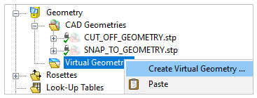
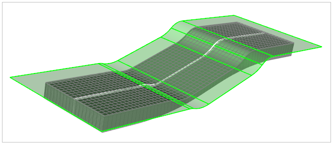
Note: The two CAD geometries are imported into ACP and shown above.
In the Virtual Geometry Properties dialog, place the cursor in the Sub Shapes field (A, below), then select CUT_OFF_GEOMETRY.stp from CAD Geometries in the Tree View.
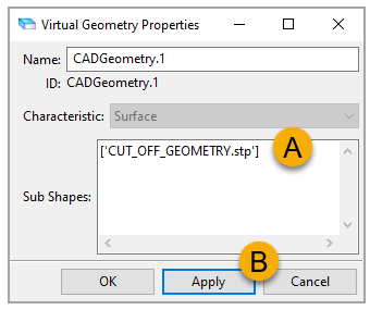
Click Apply (B, above), then close the dialog. The virtual geometry is now visible in your model.
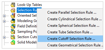
In the Tree View, right-click Selection Rule and select Create Cutoff Selection Rule.
In the Cutoff Selection Rule Properties dialog, place the cursor in the Cutoff Geometry field (A, below), then select CADGeometry.1 under Virtual Geometries from the Tree View.
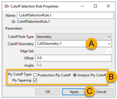
Define other properties as shown (B, above). Click Apply (C), then close the dialog.
Expand PlyGroup.1 under Modeling Groups. Right-click ModelingPly.1 and select Properties.
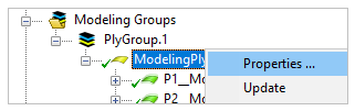
In the Modeling Ply Properties dialog, switch to the Rules tab. Under Selection rule, select CutoffSelectionRule.1 from the drop-down menu. Click Apply, then close the dialog.

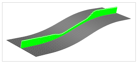
Update the Section Cut by following step 5 in the earlier section, Creating the First Modeling Ply. The result of the Cut-Off Selection Rule will be visible in your model.
Note: You can verify the final configuration of the model in ACP by counting the total sum of layers after creating the second Modeling Ply and extruding the model, wherein the sum is 18 layers. The first Cutoff Geometry removes four layers from the first Modeling Ply. Then the second Modeling Ply creates two more layers, accounting for the sum.
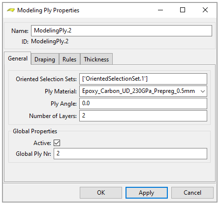
In this section, you will create a second Modeling Ply on top of the first one, extrude the composite model into a solid structure, and use a global Drop-Off material to fill the gaps between the two plies.
Define a two-layer Modeling Ply following steps 2 to 4 in the earlier section, Creating the First Modeling Ply, and using the specifications shown in the image below.
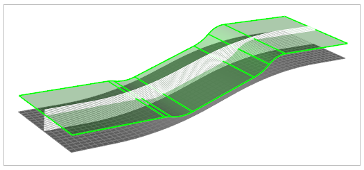
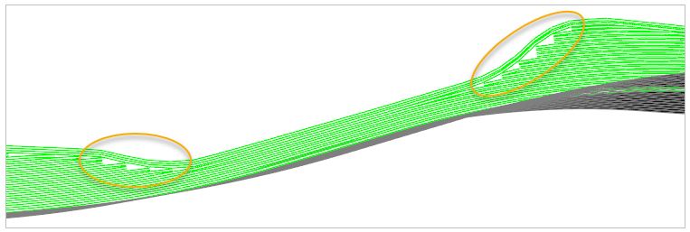
Update the Section Cut. As shown below, the second ply covers the first ply, but there are small empty pockets between the two plies.
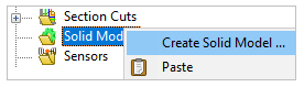
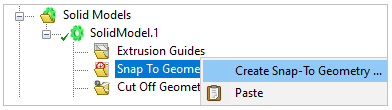
In the Tree View, right-click Solid Models and select Create Solid Model.
In the Solid Model Properties dialog, place the cursor in the Element Sets field (A, below), then select All_Elements from Element Sets in the Tree View. Select Surface Normal from the Offset Direction drop-down menu (B).
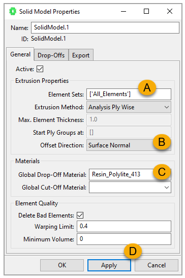
For Global Drop-Off Material, select Resin_Polylite_413 from the drop-down menu (C, above). Click Apply (D) and close the dialog. The solid structure is visible in your model.

Zoom in to the edge of the model. The empty pockets (shown below) were filled with Resin_Polylite_413 during the extrusion process. These elements are called Drop-Off elements.
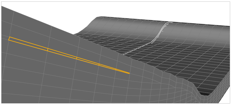
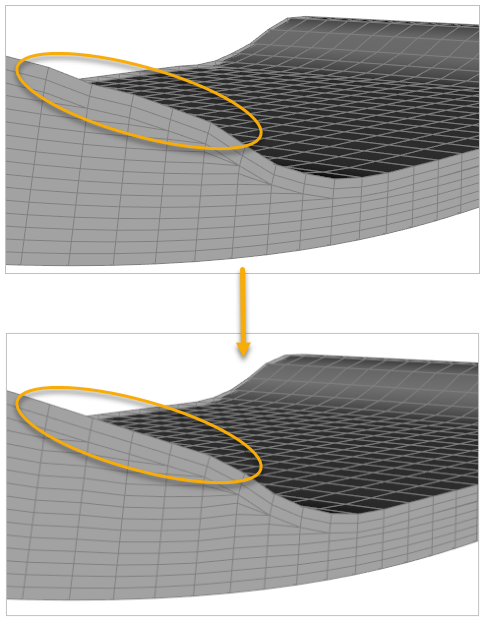
In this section, you will smooth the solid model's surface using ACP's Snap-To Geometry feature.
Create a virtual geometry, CADGeometry.2, based on SNAP_TO_GEOMETRY.stp by following steps 1 to 3 in the earlier section, Applying the Cut-Off Selection Rule.
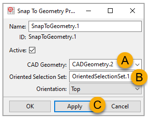
In the Tree View, expand Solid Models and SolidModel.1. Right-click Snap To Geometry and select Create Snap-To Geometry.
In the Snap-To Geometry Properties dialog, select CADGeometry.2 from the CAD Geometry drop-down menu (A, below). Choose OrientedSelectionSet.1 as the Oriented Selection Set (B). Click Apply (C), then close the dialog.
Click the Update icon on the toolbar to solve the model. The waviness in the original structure is improved: