


You can easily transfer RVE models created in Material Designer to a downstream Static Structural system. Specifically, you can transfer the finite element model of the RVE (material properties, geometry, mesh and element orientations) together with one of the six load cases used to compute linear elastic material properties. Once you have created a Material Designer system, transfer the model by doing the following:
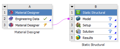
Create a new Static Structural system.
Connect the Material Designer cell to the Model cell of the Static Structural system. When you create the connection, the Mechanical system will no longer display the Geometry and Engineering Data cells. Material Designer now provides the system data.
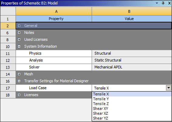
By default, the tensile load case in the X direction is transferred to Mechanical. You can specify a different Load Case, as shown below, by changing the Transfer Settings for Material Designer in the Properties pane of the Static Structural model.
To successfully complete the transfer, only the RVE Model must be defined in Material Designer. It does not matter whether you also created a Constant or Variable Material Analysis. They do not affect the transfer to Mechanical.
When connecting a Material Designer system to a Static Structural system, the following entities are imported and created in Mechanical:
Constituent Materials (The materials defined in the Engineering Data cell of the Material Designer system are automatically transferred to the Static Structural system.)
Geometry (A mesh-based geometry is created.)
Mesh
Element Orientations (depending on the RVE type)
Constraint Equations
Named Selections created by Material Designer to apply boundary conditions. (User-defined named selections are not transferred.)
Boundary Conditions
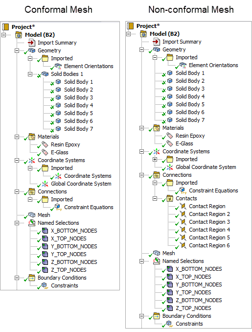
When non-conformal meshing is used, contacts are not transferred. Instead, they must be redefined in Ansys Mechanical. This happens automatically if the option Auto Detect Contact On Attach is selected, which is the default. You will find Auto Detect Contact On Attach in the Workbench Project Page, under . For more information, see Connection Group in the Mechanical User's Guide.
Note: The environment temperature defined in the Analysis Settings tool is not transferred to Mechanical.
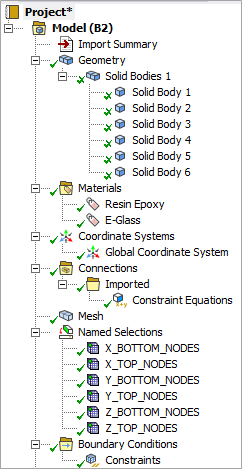
In the example shown below, the transferred objects for a UD Composite appear in the Tree Outline of Ansys Mechanical.
Here, the objects for a Woven Composite are shown in two separate examples– one for a conformal mesh and the other for a non-conformal mesh. Notice that Contacts appear under the Connections group for the non-conformal mesh.
The imported Mechanical model is fully defined and ready to be solved. You can review and post-process the solution using the various results described in the Using Results section of the Mechanical User's Guide.
Note: It is possible to see slight differences between the Material Designer and the Mechanical solutions, depending on the solver settings you choose in Mechanical– a direct versus an iterative solver type, for example.