When a Weld Lines File is specified in the Injection Molding Data setup component, you can use an Imported Material Field object to map weld lines onto the structural mesh. Specifically, you can map weld lines as element-based Named Selections in Mechanical. These Named Selections can be used for visualization and post-processing purposes as well as to assign degraded material properties in the weld regions. Not only, also the weld angle is imported and mapped as a material field.
Follow these steps in Mechanical:
Open the Materials folder as well as the Imported Material Fields object.
Either select the Imported Material Field child object or insert a new one if you already imported other material fields.
Scope the object to the geometry of interest.
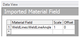
In the Data View, make sure to select the WeldLineAngle identifier.
Enable the option Display Source Points in the Graphics Control group to visualize the weld lines location as imported from the injection molding simulation.

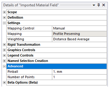
Set the Mapping Control option to Manual and the Weighting type to Distance Based Average. Then, adjust the Pinball radius in the Advanced group to control the extent of the target region around the source points. For instance, you can specify a pinball radius equal to the average element size in the weld region.
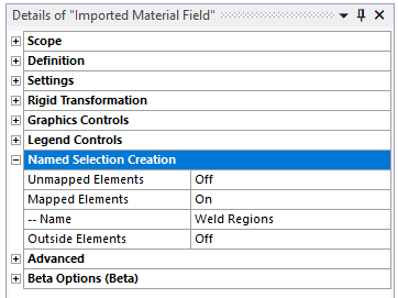
In the Named Selection Creation group, turn on the Mapped Element option and optionally provide a custom name for the Named Selection.
For more details about these Named Selections, see Data Transfer Mesh Mapping in the Mechanical User's Guide.
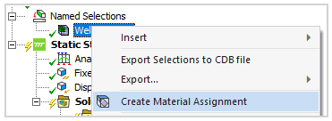
Right-click the Imported Material Field object and select the Import Material Field option from the context menu. This action maps the weld angle and creates a Named Selection for the weld regions.
Optionally, you can assign a dedicated material to the weld regions by inserting a Material Assignment, see Material Assignment in the Ansys Mechanical User's Guide.