


Monitor
With Monitor tab, you can indicate the characteristics of the monitor.
Monitor parameters are used to perform true color rendering especially in Virtual Photometric Lab.
You can improve the spectral maps' display and avoid color disparity for a given spectral map according to the monitor.
However, keep it mind that each display has its own gamut and color limitations.
Indeed, a standard display is based on 3 colors mixing (Red/Green/Blue). All displayable colors inside this environment are related to the display’s luminance and colors capacities. This environment is called RGB gamut.
Once a natural color has to be displayed on the monitor but is outside of this gamut, the color is approximated to the closest displayable color contained in the gamut.
Each display has its own gamut. That is why it is important to perform a characterization of the display to check its limitation, and a calibration of the display to obtain a better color correlation (a better match between the color comprised in the gamut and the real color).
A correction usually has to be applied to the monitor for virtual results to better fit reality. This correction can be performed from the preferences and is done by setting the chromaticity values (colors perimeters), the white point luminance (maximum luminance that the monitor can reach) and the gamma correction (correlation between real and displayed colors).
Display
In Display box, you must select the display type.
Depending on your screen specification, different types of displays are available:
The Standard display is selected by default. It is the mode that is selected if you do not have one of the two others monitors.
The SIM2 HDR display allows you to display results on SIM2 HDR screens.
Note:- This display type is only available for Virtual Reality Lab.
- When selecting SIM2 HDR display, other parameters are not available because specific settings are directly applied with this display type.
When selecting SIM2 HDR display with Virtual Reality Lab, it is not possible to activate Human Vision functions as Glare.
Note: To avoid any display problems, SIM2 HDR monitor has to be dedicated for rendering and a standard monitor for interface. You should not create any immersive view directly from a HDR screen.
The JVC HDR projector type allows you to display results on a JVC HDR projector.
When selecting JVC HDR projector type, another list appears corresponding to the screen density available for this projector.
Note: When selecting Gain 1.0 / Custom white point luminance, you must select the white point luminance measured on your projector.The HDR10 display allows you to display results on screens that are compatible with the HDR10 standard.
Note:- This display type is only compatible with Virtual Reality Lab and requires a restart of the application to be functional.
- Depending on your display, the chromaticity values may be automatically obtained from the screen.
- With this mode, gamma correction does not need to be defined.
Before displaying results on your HDR display, follow this procedure to make sure your Windows and GPU settings are correctly configured to allow High-Dynamic-Range imaging.
Chromaticity Values
In Chromaticity values table, you can change the chromaticity values x and y of Red, Green, Blue and White to obtain a better color fitting between the display's colors and reality.
The Red, Green, Blue chromaticity values represent the monitor's gamut.
The white chromaticity values represent the monitor's white point.
To measure and report the correct chromaticity values, you can follow the Display Characterization process or contact ANSYS support.
The default values represent the standard color space, sRGB. Those points are used for gamut clipping. Points outside the gamut are automatically clipped on the edge of the gamut.
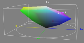
The shape itself and the shades of color represents the gamut of the screen.
The point 2 corresponds to the best color approximation that could be displayed on the screen.
Gamma Correction
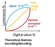
The intensity of light generated by a physical device varies non-linearly. This non-linearity must be compensated to achieve a correct restitution of intensity.
A conventional CRT display has a powerlaw response to voltage. That means a correction is applied onto the intensity produced by the display in order to obtain a standard value.
The applied voltage is usually raised to a 2.5 power. The numerical value of the exponent of this power function is colloquially known as gamma.
In Correction Type group box, select the way to perform gamma correction.
Fitted Gamma: the gamma correction is performed by using the table below.
You can define a different value of Gamma and Gain for each primary color but keeping the same value is recommended. Gamma is given by the formula: R = (G x R' + 1 - G)y where R: relative luminance, G: Gain, R': Relative Digital value, y: Gamma Gamma and Gain values can be obtained from your monitor's manufacturer.
SMPTE 2084: defines the gamma correction according to the specific formula from the SMPTE ST 2084:2014 standard.
The SMPTE ST 2084: 2014 standard is used by HDR screens using the HDR10 or Dolby Vision certification.
Custom Gamma: RGB Gamma is given by 18 points on each Red, Green, Blue colors. This option allows you to adapt a specific gamma curve for each screen.
To use this option, you must follow the Display Characterization process first.
White Point Luminance
In White Point Luminance, you can type the white luminance level which gives the monitor's dynamic.
The White Point Luminance tells Speos the maximum luminance of the screen. To obtain this value, refer to your monitor's data sheet or measure it by following the Display characterization process.
The White Point Luminance value is then used as a default value for the scale. In the Maximum Level Controller checking the 1:1 scale option allows Speos to saturate all luminance values that are above this white point luminance value (which corresponds to screen's maximum luminance capability.)
If you set a White Point Luminance of 100cd/m2 for example, it means the maximum luminance that can be displayed is 100cd/m2. If you check the 1:1 scale option, it means all information from the map that is above 100cd/m2 is saturated to white.