


Anisotropic BSDF Surface Overview
With Anisotropic BSDF Surface, you can simulate both isotropic and anisotropic surfaces from goniometric measurement data.
With following diagram you can view angle definitions for incoming and outgoing directions according to the surface normal (Z) and the fixed anisotropic vector.
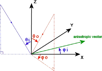
Z vector |
Surface normal |
X vector |
Constructed for a given incoming photon as the projection of its direction on the surface plane |
Y |
Computed from X and Z |
Anisotropic vector |
The Anisotropic vector is the orientation vector of the BSDF on the geometry. It defines an axis on the surface used as the origin when calculating the Anisotropic angle. It directs the surface when the vector given in the file is not in the tangent plane at the impact point, an orthogonal projection of it is used instead. You can modify the anisotropic vector in the X, Y and Z boxes under Anisotropy vector. The anisotropic vector is stored in .anisotropicBSDF files and is defined by the global coordinate system. |
Anisotropic angle Phi_i |
The anisotropic angle is the angle between the incidence plane and the anisotropic vector. When the vector is in the incidence plane, phi=0°. Angle between X and the anisotropic vector using trigonometrical convention (Phi_i is positive on the diagram) Setting the Phi incidence angle value does not impact the incidence angle visualization in the XYZ axis system. |
Theta_i |
Incidence angle |
Output direction (Theta_o, Phi_o) |
Displayed in red and is given using standard spherical coordinates in the X,Y,Z axis system |
Angles ranges:
Theta_i must be in the [0° 90°] interval.
Theta_o must be in the [0° 90°] interval for reflection and in the [90° 180°] interval for transmission.
Phi_i and Phi_o must be in the [0° 360°] interval.