


Parameters of Interpolation Enhancement
View Control
In View control box, you must select Full view, Specular part or Diffuse part to switch to a specular or a diffuse view of the BSDF. This helps to visualize the boundary between the specular and the diffuse parts.
Specular Versus Wavelength
This function has to be used if both of the following conditions are true:
Colored surface with specular or gaussian peak,
BRDF measured with a monochromatic source (one laser or one Xe filter) and an integration sphere system.
If you follow the standard measurement process (spectrum as input of the BRDF measurement), then the gaussian/specular part will have the same spectrum than the diffuse part.
The problem is that it may not be the case in reality. For example, a car paint can have a diffuse color, but the specular reflection is not colored (white). The Keep specular constant versus wavelength option allows you to solve this issue. If checked, then gaussian and specular reflections have no more wavelength dependency.
The limit between specular/gaussian and diffuse is the cone defined while doing "BSDF enhancement" (in Cone properties > Angle).
Base Wavelength: Wavelength of laser source.
Cone Properties
In Cone properties box, you must use Angle and Height of cone sliders to adapt the BSDF.
Parameters
Number of cones depend on whether there is transmission or not, number of incidence angles and number of wavelength or anisotropic angles.
In the Parameters box :
Three modes (Reflection, Transmission and Retroreflection) are available from the editor. These modes allow you to separate the BSDF's different contributions to correctly adjust the interpolation cones. Depending on the nature of the BSDF measured, select one of these modes to visualize and interact with its contribution in the model.
Changing the Incidence values allows you to change the incidence sample.
Changing Wavelength values allows you to change the wavelength sample (or anisotropic sample).
The Refractive indices can only be specified when the sample contains transmission. They allow to indicate the difference of density between the sample and the medium surrounding it.
n1 corresponds to the refractive index of the first medium light passes through.
n2 corresponds to the refractive index of the sample measured.
Examples
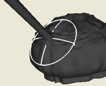 |
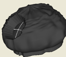
View Control: Full view Cone properties: Angle: 25°; Height: 47 The height of the cone seems to be correct. It cuts the BSDF at the base of the specular peak. The angle of the cone is too wide compared to the width of the specular peak. This may reduce the calculation speed. |
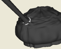 |
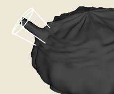
View Control: Full view Cone properties: Angle: 6°; Height: 47 With an angle reduced down to about 6°. |
Make sure specular and diffuse parts look both fine.
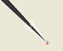 |
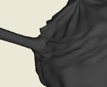
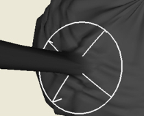
View Control: Specular part Cone properties: Angle: 6°; Height: 47 |
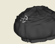 |
View Control: Diffuse part Cone properties: Angle: 6°; Height: 47 |
When the height is too small, you can see a crater in the diffuse part. |
 View Control: Diffuse part |
You must increase the height until the crater disappears. |
When the height is too big, you can see a bump on the diffuse part. |
 View Control: Diffuse part |
You must decrease the height until the bump disappears. |
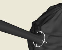
When the angle is too small in the Full view, the cone totally disappears in the BSDF shape. |
 View Control: Full view |
You must increase the angle to make it only slightly larger than the specular peak. |
It happen the angle is too large. |
 View Control: Full view |
The surface of the base of the cone is large compared to its intersection with the specular peak. This situation does not provide bad results but you must reduce angle to have faster performances. |
Software performs faster if the base of the cone is only slightly larger than the specular peak. |
 View Control: Full view |