


Understanding LiDAR Sensor Parameters
This page describes the parameters to set when creating a static, scanning or rotating LiDAR sensor.
A LiDAR sensor definition can be broken down into several parts corresponding to each component of the LiDAR system: the system definition, the source definition and the sensor definition.
System Definition
The system definition corresponds to the definition of the LiDAR physical module and its emission pattern.
-
Axis System: the system's axis system defines the position and orientation of the "physical" LiDAR module. This axis is only required for rotating LiDARs as it is used as the revolution axis of the system.
During the simulation, the Y vector of this axis is used as reference to allow the other axes (the source's and sensor's axes) to revolve around it.
-
Trajectory file: a trajectory describes the different positions and orientations of features in time. The Trajectory file is used to simulate dynamic objects.
Note: For more information, see Trajectory File. Firing Sequence: firing sequence files are files used to describe a LiDAR's emission pattern.
Two types of firing sequence files are available in Speos allowing you to define the emission pattern of a scanning or a rotating LiDAR.Note: For more information, see Firing Sequence Files.
Source Definition
The source definition corresponds to the definition of the emitter channel of the LiDAR.
-
Axis system: sets the position and orientation of the source channel.
Note: When using an intensity distribution file, verify the orientation of the IES file to correctly orient the beam which changes according to the IES type (IESNA type A B or C).Example:
Source X direction = X axis
Source Y direction = Y axis
IES A IES B IES C _LiDAR_Source_IES_A.png)
_LiDAR_Source_IES_B.png)
_LiDAR_Source_IES_C.png)
-
Spectrum: for static LiDAR source, the spectrum is monochromatic. Only one wavelength must be defined to set the spectral excursion of the LiDAR.
For scanning or rotating LiDARs, the spectrum can either be monochromatic or defined by a spectrum file (*.spectrum) as input.
-
Intensity: for static LiDARs, the intensity of the source is defined using an IES (*.ies) or eulumdat (*.ldt) file.
For scanning or rotating LiDARs, the intensity of the source can be defined either by using an intensity distribution file (*.ies or *.ldt file) as input or by manually defining an asymmetrical gaussian profile.
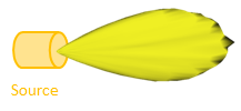
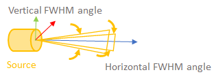
Source defined by IES file Source defined with a gaussian profile - Energy: the source energy corresponds to the laser pulse energy expressed in Joules (J).
- The Minimum intensity threshold is the threshold under which the signal
of the LiDAR source is not taken into account. This helps LiDAR differentiate what should be used
or ignored to calculate LiDAR's field of view. Note: For a static LiDAR, the energy and minimum intensity threshold are defined in the interface.
For scanning or rotating LiDARs, only the pulse energy must be defined in the scanning sequence file.
Sensor Definition
The sensor definition corresponds to the receiver channel of the LiDAR.
- Axis System: sets the position and orientation of the sensor channel.
-
The Optics section allows you to model the optical system in front of the imager.
- Distortion file: the .OPTDistortion file is used to introduce/replicate the optical distortion of the lens.
- The Transmittance corresponds to the capacity of the lens to allow the light to pass through.
- The Focal length defines the distance between the center of the optical system to the focus.
-
The Pupil is the diameter of the LiDAR sensor'saperture.
According to the Pupil size, rays coming with the same direction are not integrated in the same pixel._LiDAR_Pupil_Diameter.png)
If you keep increasing the pupil size, you will observe blur as shown below:
_LiDAR_Pupil_Diameter_0.5.png)
_LiDAR_Pupil_Diameter_1.0.png)
_LiDAR_Pupil_Diameter_10.0.png)
Pupil = 0.5 Pupil = 1.0 Pupil = 10.0 - The Horizontal and Vertical FOV correspond to the fields of view calculated by the sensor using the Focal Length, Distortion File, Imager Width and Height.
-
The Imager represents the LiDAR sensor (receiver channel).
- The Imager Width and Height correspond to the
horizontal and vertical size of the sensor. Note: For scanning and rotating LiDARs, only the Width and Height of the imager must be defined as the sensor is a one-pixel sensor.
- The Horizontal and Vertical Pixels represent the sensor resolution.
- The Imager Width and Height correspond to the
horizontal and vertical size of the sensor.
- Range and accuracy
- The Start and End values represent the distance from, and up to which the LiDAR is able to operate and integrate rays.
-
The Spatial accuracy defines the discrimination step used to save the Raw time of flight signal.
This magnitude is directly linked to the hardware capability of the LiDAR system regarding its distance resolution and sampling frequency.
Timestamp resolution can be converted to a spatial resolution, using the time of flight.
The Aiming area allows you to define the position, size and shape of the LiDAR's protective sheet.
When Aiming area is set to False, the Aiming area inherits the Axis system of the sensor (receiver), and its dimensions are automatically calculated according to the input data (Pupil).
Note: For more information, see LiDAR Sensor Aiming Area Parameters.