


Firing Sequence Files
This page describes the format of firing sequence files, used to define the scanning and/or rotation pattern of a LiDAR system.
Description
Firing sequence files are used to describe a LiDAR's emission pattern. These files embed several information like the firing time, firing angles and source power, that will be used during the simulation to draw the scanning sequence.
Two types of firing sequence files are available in Speos allowing you to define the emission pattern of a scanning or a rotating LiDAR.
Scanning Sequence File
Scanning Sequence File Overview
Scanning sequence files describe the horizontal and vertical emission pattern for one beam or multiple beams of the LiDAR. They are required for both scanning and rotating LiDAR sensors.
- *.txt Scanning Sequence File which describes:
- the power of each beam
- *.OPTScanSequence Scanning Sequence File which describes:
- the power of each beam
- the intensity profile and intensity distribution of each beam
- the emissive surface shape of the beam
- the spectrum of each beam
For more information on how to generate a scanning sequence file, refer to Generating a Scanning Sequence File.
*.OPTScanSequence Scanning Sequence File Content
The *.OPTScanSequence scanning sequence file comprises the following parameters:
- Type of pulses: DIRAC, Gaussian, Rectangular, Triangular
Width of pulse (s): duration of one pulse in seconds (s), Δt (only for Gaussian, Triangular, Rectangular pulse types)
Note: When using the Dirac pulse type, the Width of pulse is skipped.
_Lidar_Pulse_Type_Triangular.png) |
_Lidar_Pulse_Type_Rectangular.png) |
_Lidar_Pulse_Type_Gaussian.png) |
| Triangular pulse type | Rectangular pulse type | Gaussian pulse type |
- Shooting Time (s): time when the pulse is emitted in seconds (s)
- Pulse energy (J): Energy of the pulse in Joules
Pulse type: From pulses, DIRAC, Gaussian, Rectangular, Triangular
Note: From pulse means that the Pulse type inherits the Type of pulses value.Pulse width (s): duration of one pulse in seconds (s), Δt (only for Gaussian, Triangular, Rectangular pulse types)
Note: If you enter a Pulse width value different from the Width of pulse value, the Pulse width has priority.Note: When using the Dirac pulse type, the Width of pulse is skipped.- Azimuth angle (°): Azimuth angles within the range [0;360[ expressed in degrees
Elevation angle (°): Elevation angles within the range [-90;90] expressed in degrees
Note: Azimuth and elevation angles are expressed with respect to the source's axis system of the LiDAR sensor.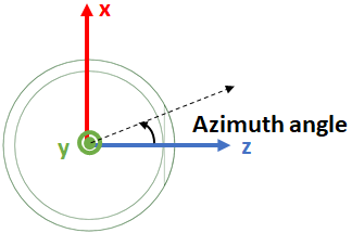
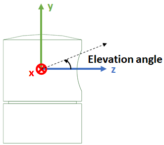
Azimuth angle (horizontal pattern) Elevation angle (vertical pattern) - Position X Y Z (mm): Starting position of the beam with respect to the source's axis system of the LiDAR sensor. That means the beam can be offset.
- Emissive Surface Description: corresponds to the emissive surface of the beam.
- Surface shape: Point, Rectangular, Elliptic
- Width: width of the beam (for Rectangular and Elliptic shapes)
- Height: height of the beam (for Rectangular and Elliptic shapes)
- Psi angle (°): corresponds to the rotation of the surface shape around the Z axis
- Intensity Description
Intensity type: From source definition, Sampled, Gaussian
If you set From source definition, the Source - Intensity section's parameters from the LiDAR sensor definition are used.
If you set Sampled, define an Intensity file (IES file)
If you set Gaussian define the three following Gaussian parameters.
- Intensity file: IES file that will be converted into a readable intensity distribution when generating the *.OPTScanSequence (or *.txt) file. The intensity value is defined on 2π steradian.
- Gaussian FWHM along X and Y (°): Gaussian intensity distribution of the beam
- Gaussian total angle (°): Total angle of the beam for a Gaussian intensity distribution
_Scanning_Sequence.png)
- Spectrum description
Spectrum type: From source definition, Sampled, Monochromatic
If you set From source definition, the Source - Spectrum section's parameters from the LiDAR sensor definition are used.
If you set Sampled, define an Spectrum file
If you set Monochromatic defined Wavelength (nm)
- Spectrum file: Specific spectrum file for the beam
- Wavelength (nm): wavelength for monochromatic spectrum type
*.txt Scanning Sequence File Content
- Pulse Type: DIRAC, Gaussian, Rectangular, Triangular
Width of the pulse Δt in nano seconds (ns) (only for Gaussian, Triangular, Rectangular pulse types)
Note: When using the DIRAC pulse type (line 3), the Width of the pulse (line 4) is skipped, meaning no blank line.Triangular pulse type Rectangular pulse type Gaussian pulse type - Fire_time_N: Shooting time in micro seconds (μs)
- Fire_pulse_energy_N: Pulse energy in Joules (J)
- Azimuth_angle_N: Azimuth angles within the range [0;360[ expressed in degrees
Elevation_angle_N: Elevation angles withing the range [-90;90] expressed in degrees
Note: Azimuth and elevation angles are expressed with respect to the source's axis system of the LiDAR sensor.Azimuth angle (horizontal pattern) Elevation angle (vertical pattern)
| Format Description | Example |
|---|---|
|
|
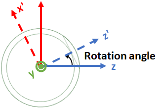
Rotating Sequence File
Rotating sequence files describe the rotation pattern of the LiDAR system. The rotating sequence file and scanning pattern file need to be combined to model the definition of a rotating LiDAR. Indeed, with this configuration, the scanning pattern (defined in the scanning sequence file) is repeated sequentially for each rotation step of the LiDAR (defined in the rotating sequence file).
- Rotation time
Note: The rotation time is only indicative, it does not impact the simulation.
- Azimuth angles within the range [0;360]
 |
| Azimuth angles - Rotating LiDAR rotation step |
| Format Description | Example |
|---|---|
|
|