


Understanding Mapping
This page describes the different types of mappings available and the mapping process.
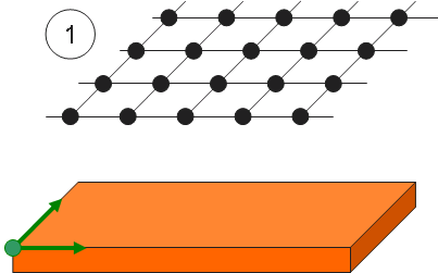
The mapping determines the distribution of the patterns on the support.
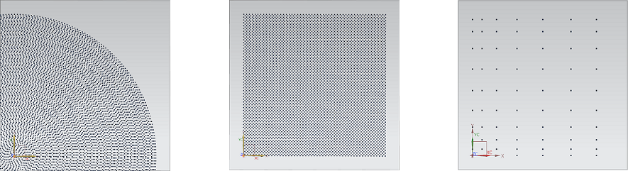
Different mapping types are available. Each type describes a way to create a virtual grid that is going to be projected on a part’s surface.
When creating a 3D texture you can choose to use:
Automatic mappings: Rectangular, Circular, Hexagonal, Variable Pitches. These mappings are automatically calculated and you only have to set a few parameters to obtain the desired distribution.
Mapping Files : Mapping files are .txt files containing all the information needed to generate the mapping. It allows you to generate a completely customized mapping and/or save a mapping you designed with the automatic mappings and use it in another CAD system where Ansys software is integrated.
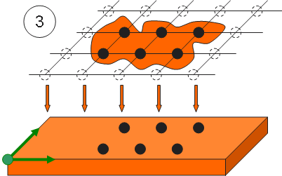
Example of the mapping process using various mapping options:
 |
 |
 |
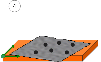 |
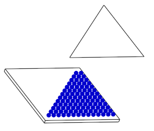
Mapping: a virtual grid is created using standard parameters (distance between patterns, mapping length, etc.).
Filtering: a quilt or a face is used to define the grid limitations.
All the patterns included in the limited grid are projected along the Z direction on the first encountered surface of the selected part.
Shift: an offset (shift along Z) can be applied on the projected patterns.
Limiting Surface
The Limiting Surface
_Mapping_Limiting_Surface.png) allows you to apply a surface on the geometry on which you apply the 3D texture to limit the 3D texture to that specific surface.
allows you to apply a surface on the geometry on which you apply the 3D texture to limit the 3D texture to that specific surface.
_3D_Texture_Limiting_Surface_2_Faces.png) |
_3D_Texture_Limiting_Surface_1_Face.png) |
| Limiting Surface composed of two faces | 3D Texture applied on only one face |
Offset Surface
The Offset Surface
_Mapping_Offest_Surface.png) is a shift surface that
allows you to apply an offset to the projected patterns along the Z direction according to the
origin of the 3D texture's axis system.
is a shift surface that
allows you to apply an offset to the projected patterns along the Z direction according to the
origin of the 3D texture's axis system.
The Shift scale helps you define the offset.