


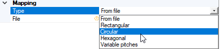
Creating a Circular Mapping
-
From the Mapping Type
drop-down list, select Circular.
-
Set the following parameters:
Radial distance between patterns

Mapping radius

Distance between rings

X angular offset

-
If you want to limit the mapping to a specific area, shape:

- If not already done, import or create a face in the current assembly.
-
In the 3D view, click
_Mapping_Limiting_Surface.png) and select the
imported/created object to limit the 3D texture distribution to that specific face.
and select the
imported/created object to limit the 3D texture distribution to that specific face.
-
If you want to define an offset along Z direction on the projected patterns:

-
In the 3D view, click
_Mapping_Offest_Surface.png) and select the support on
which to apply the offset.
and select the support on
which to apply the offset.
- Type a value in Offset surface ratio to determine the offset of your patterns.
-
In the 3D view, click
-
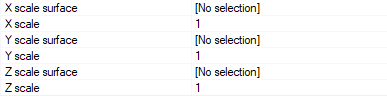
If you want to define three scale factors to set the size of each pattern independently on the 3 axes (X, Y, Z):
-
Click
_Mapping_X_Scale_Surface.png) to select an X scale surface,
to select an X scale surface, _Mapping_Y_Scale_Surface.png) to select a Y scale surface and
to select a Y scale surface and _Mapping_Z_Scale_Surface.png) to select an Z scale surface.
to select an Z scale surface.
The scaling factor to apply to a specific mapping point is defined by the height of the point of this surface, at the corresponding coordinates (X,Y).
Note: You can define a specific scale on all three independent axes (X,Y,Z axes) or on one axis only (only on X for example).
-
Click
-
Click Compute
_Compute.png) to verify the 3D texture
distribution.
to verify the 3D texture
distribution.
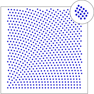
A progress bar appears and allows you to stop the compute if necessary. At the end of the compute, the Dots appear on the support indicating the patterns' location on the surface.
Note: After saving and opening again the project, you need to compute again the 3D Texture to display the pattern in the 3D view. Speos does not store the meshing information to avoid performance issues when saving and opening projects. -
To fully compute and visualize the patterns on the support:
-
Click Optional or advanced
settings
_Speos_Options.png) .
.
_Mapping_Preview.png)
-
Adjust the X size, Y size and Z
size of the preview box to see it appear in the 3D view.
-
Click Optional or advanced
settings
The ciruclar mapping is created and an OPT3D Mapping file is automatically generated and stored in the Speos inputs files folder.