


Creating a Thermic Source using a Temperature Field File
A thermic surface can define a source for which the total flux and the spectrum are defined by the source's temperature and the optical properties of the support geometry. This page shows how to create a Thermic Source using a temperature field file.
To create a Thermic Source using a Temperature Field File:
-
From the Light Simulation tab, click Thermic Source
_Source_Thermic.png) .
.
-
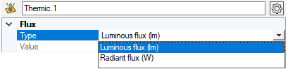
From the Flux drop-down list:
-
Select Luminous flux (lm) to set the flux in lumens.
Luminous flux is the photometrically weighted radiant energy, that is to say measuring the total radiant energy across the spectrum, weighted by the sensitivity of the human eye to different wavelengths.
-
Select Radiant flux (W) to set the flux in Watt.
Note: You cannot edit the flux values, they are automatically computed.The flux value depends on the blackbody temperature and the surface optical properties and is determined by calculating the emittance's integral on the geometry of the source.
-
-
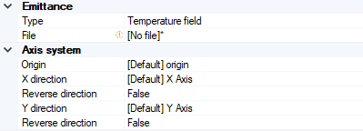
In Emittance, from the Type drop-down list,
select Temperature field.
-
Double click in the file field to browse and load an .OPTTemperatureField file.
Note: The .OPTTemperatureField file format includes description line, number of summits (Ns), number of triangles (Nt), coordinates x,y,z of summits (x Ns), coordinates l,m,n of normals (x Ns), index of summits of each triangle (x Nt), temperature of each triangle (x Nt). -
To orientate the file, set its axis system by clicking in the 3D view one point for the origin point and two lines for X and Y directions or click
_Axis_System_Autofill.png) and select a coordinate
system to autofill the Axis System.Note: If you define manually one axis only, the other axis is automatically (and randomly) calculated by Speos in the 3D view. However, the other axis in the Definition panel may not correspond to the axis in the 3D view. Please refer to the axis in the 3D view.
and select a coordinate
system to autofill the Axis System.Note: If you define manually one axis only, the other axis is automatically (and randomly) calculated by Speos in the 3D view. However, the other axis in the Definition panel may not correspond to the axis in the 3D view. Please refer to the axis in the 3D view.If you need to adjust the direction of the vectors, use the Reverse direction option.
-
-
In Surface optical
properties, from the Type drop-down
list:
_Source_Thermic_Surface_Optical_Properties_Definition.png)
- Select Mirror for a perfect specular surface and edit the Reflectance value if needed.
- Select Optical Polished for a transparent or perfect polished material (glass, plastic).
Select Library and double-click the file field to browse and load a SOP file.
If you want to edit the file, click the file and click Open file to open it with a surface optical property editor.
Select Plug-in, and click Browse to select a custom made *.sop plug-in as File and the Parameters file for the plug-in.
Note: Make sure each plug-in created has a different GUID._Source_Thermic_Surface_Properties_Plugin.png)
For more information, refer to Surface State Plugin.
-
From the Intensity Type
drop-down list, select the intensity distribution of the source:
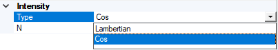
- Select Lambertian for a uniform distribution.
- Select Cos for a distribution that follows a cosine law at nth order and in N set the order of the cosine law.
-
In Optional or advanced settings
_Speos_Options.png) :
:
- Adjust the Number of rays and Length of rays (in mm) to display in the 3D view.
- If you want to display the meshing of the temperature field file in the 3D view, select Meshing or Bounding box.
-
Click Compute
_Compute.png) to validate the thermic source
definition.
to validate the thermic source
definition.
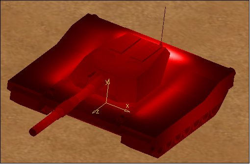
The Thermic Source is created and appears in the Simulation panel and in the 3D view.
 |
| Temperature field thermic source (GUI view) |
|
| Temperature field thermic source (simulation result) |