


Creating a Geometric Rotating LiDAR Simulation
Creating a Geometric Rotating LiDAR simulation allows you to perform field of view studies. A field of view study allows you to quickly identify what can or must be optimized (for example, the number, position and direction of sensors) in a LiDAR system.
To create a Geometric Rotating LiDAR Simulation:
A sensor must already be created.
From the Light Simulation tab, click
_Lidar_Geometric_Rotating_Lidar_02.png) .
.
In the 3D view or from the tree, click
_Simulation_Selection_Geometry.png) to select the
geometries for which you want to calculate the distance to the rotating LiDAR.
to select the
geometries for which you want to calculate the distance to the rotating LiDAR. Your selection appears in the Geometries list.
Note: In some cases, using geometries that have no optical properties applied for simulation can lengthen the simulation's initialization time.In the 3D view click
_Simulation_Selection_Sensor.png) and from the tree
select the previously created LiDAR sensor(s).
and from the tree
select the previously created LiDAR sensor(s).Your selection appears in the Sensors list.
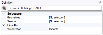
From the Visualization drop-down list, select which type of results you want to display in the 3D view:
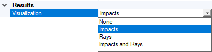
- None
- Impacts
- Rays
- Impacts and Rays
In the 3D view, click Compute
_Compute.png) to launch the simulation.
to launch the simulation.
The simulation is created and results appear both in the tree and in the 3D view.
Depending on the visualization type selected, impacts and /or rays are displayed in the scene, allowing you to visualize the LiDAR's field of view and viewing range. The distance from the LiDAR to the detected object is represented with a color scale.