Advanced Sharp Cutoff Beam Parameters
This page describes the parameters used to create a Sharp Cutoff beam in advanced mode.
In Advanced Mode, you control the light distribution on the target per point on facet. That means you can apply a different set of parameters to different points of the facet. The points are defined by the intersections of the control planes with the surface.
Control Planes
The control planes determine the intersection points made with the facet. These intersections generate points that allow to apply different parameters on different areas of a same facet.
 |
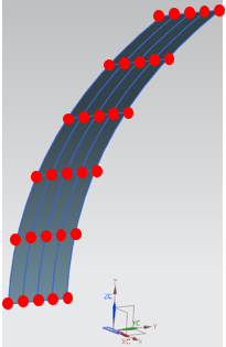 |
| Control planes | Points created on the facet by the intersection curves of the control planes and the facet. |
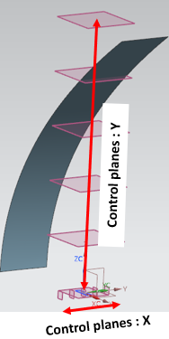
- X corresponds to the direction of the grid orientation axis. The vertical control planes are placed along X.
- Y corresponds to the direction normal to the plane made with the grid's projection and orientation. The horizontal control planes are placed along Y.
Position
The control planes need to be defined and positioned independently on X (horizontal axis) and Y (vertical axis).
 |
 |
| X axis | Y axis |
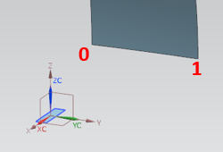
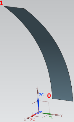
To position the control planes, you need to define a ratio (X and Y value) between 0 and 1.
0 corresponds to the negative direction of the axis, and 1 to the positive direction of the axis.
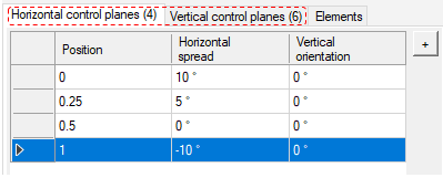
Reflected Rays Direction
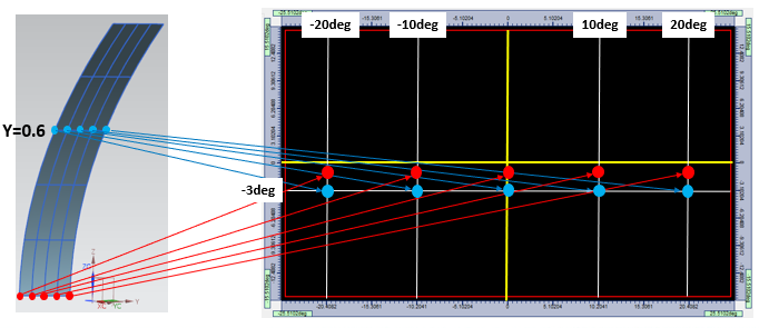
- Horizontal spread drives the direction of the reflected ray along the horizontal axis. The value to set is expressed angularly (in degrees), 0° corresponding to the same direction as the target axis.
- Vertical spread drives the direction of the reflected rays along the vertical axis. The value is expressed angularly (in degrees), 0° corresponding to the same direction as the target axis.
Horizontal and Vertical Spread values between control planes are linearly interpolated.
Control planes orientation
The Vertical orientation adjusts the horizontal spread size of the beam on the target.
This parameters allows you to adjust the extent of the beam's emission and therefore to generate different emission patterns (wider or narrower emission).
 |
 |
 |
 |
|
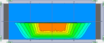
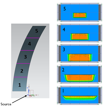
Standard Sharp Cutoff (Simplified behavior) Vertical Orientation to 0° The farther the facets are from the source, the less respected the Horizontal Spread. |
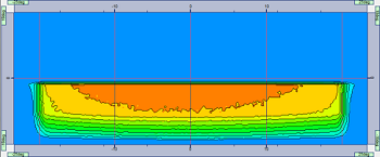
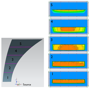
Sharp Cutoff in Advanced Mode Vertical Orientation = Horizontal Spread. The Horizontal Spread is respected on the target and the shape of the facet is modified with respect to optical principles. The result geometry takes space of adjacent facets and you need to consider the balance beam pattern and the size/shape of each facet. |
Cutoff line orientation
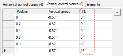
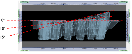
The Tilt allows you to define the orientation of the cut-off line for each area of the facet defined by the control planes.
A different value can be applied to each control plane to create a progressive tilt.