


Creating Dynamic Light Box
The following procedure helps you create a dynamic Inverse simulation of a Light Box.
In this procedure, only the Light Box will move according to the Trajectory file you input. Anything you add in the simulation (geometries, sources, sensors) that is not included in the Light Box will be static.
In other words, all geometries included in the Light Box will move together. However, we recommend
you to define one Light Box per trajectory. For instance:
- the geometry of a car would have its own trajectory - shift for instance - and should be placed inside one Light Box.
- the geometries of the wheels would have their own trajectory - rotation and shift for instance - and should be placed inside another Light Box.
Note: The procedure highlights the main steps with a focus on the dynamic parameters. If you need more
precision on the different features click the related feature links.
To create a dynamic Light Box:
-
From the Light Simulation tab, click System
_Sensor_Camera.png) > Camera .
> Camera .
-
From the Mode drop-down list, select
Photometric/Colorimetric to enable the advanced definition.
_Sensor_Camera_Mode_Photometric_Definition.png)
-
Define the Camera sensor parameters, and more specifically:
- the Integration: corresponds to the time needed to get the data acquired by one row of pixels.
- the Lag time: corresponds to the time difference between two rows of
pixels to start the integration.
_BETA_Sensor_Camera_Acquisition_Definition.png)
Note: In this procedure example, the Camera sensor is static. You do not have to input a Trajectory file. -
From the Light Simulation tab, click
_Speos_Light_Box_Export.png) .
._Speos_Light_Box_Export.png)
-
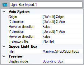
From the Light Simulation tab, click
_Speos_Light_Box_Import.png) .
.
-
From the Light Simulation tab, click Inverse
_Simulation_Inverse.png) .
._BETA_Simulation_Inverse.png)
-
Click Compute
_Compute.png) to launch the
simulation.
to launch the
simulation.