


Creating Moving and Flickering Surface Source
The following procedure helps you create a dynamic Inverse simulation of a moving and flickering Surface source.
Note: The procedure highlights the main steps with a focus on the dynamic parameters. If you need more
precision on the different features click the related feature links.
To create a flickering Surface source:
-
From the Light Simulation tab, click System
_Sensor_Camera.png) > Camera .
> Camera .
-
From the Mode drop-down list, select
Photometric/Colorimetric to enable the advanced definition.
_Sensor_Camera_Mode_Photometric_Definition.png)
-
Define the Camera sensor parameters, and more specifically:
- the Integration: corresponds to the time needed to get the data acquired by one row of pixels.
- the Lag time: corresponds to the time difference between two rows of
pixels to start the integration.
_BETA_Sensor_Camera_Acquisition_Definition.png)
Note: In this procedure example, the Camera sensor is static. You do not have to input a Trajectory file. -
From the Light Simulation tab, click Surface
_Source_Surface.png) .
._Source_Surface_Definition_Full.png)
-
Define the Surface source parameters,
and more specifically:
- the Flux variation file: *.json file that defines the samples for one period representing the variation of the relative flux of the source with time.
- the Relative lag: represents the relative time along the period when the source
starts to emit light. That means the relative lag includes a temporal shift of the time
period.
_Source_Surface_Optional_Advanced_Settings.png)
-
From the Light Simulation tab, click
_Speos_Light_Box_Export.png) .
._Speos_Light_Box_Export.png)
-
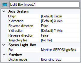
From the Light Simulation tab, click
_Speos_Light_Box_Import.png) .
.
-
From the Light Simulation tab, click Inverse
_Simulation_Inverse.png) .
._BETA_Simulation_Inverse.png)
-
Click Compute
_Compute.png) to launch the
simulation.
to launch the
simulation.