


Source Diode
The source diode model can be used to define one diode, a 1D array of diodes, or a 2D array of diodes.
The parameters are:
Angular distribution:
Each diode has an intensity distribution given by:

where
- θx is measured in the XZ plane as the angle the projected ray vector makes with respect to the z-axis. θx is an angle in degrees.
- θy is measured respectively in the YZ plane as the angle the projected ray vector makes with respect to the z-axis. θy is an angle in degrees.
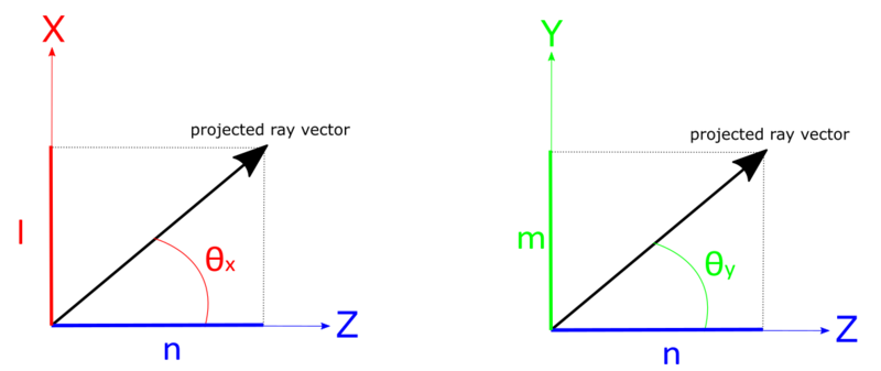
- l, m and n are the direction cosines of the ray vector.
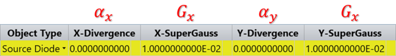
- αx and αy are the user-defined XZ and YZ divergence angle in degrees.
- Gx is the "supergaussian" factor for the X direction, with similar definitions for the Y subscripted values. Note if Gx is 1.0, then a typical Gaussian distribution results.Both Gx and Gy must be ≥ 0.01 and ≤ 50.0.Gx (X supergaussian factor) can be used to change the angular distribution of the Source Diode using a super ellipse function.
How to define αx from θfwhm ?
Most laser diode manufacturers specify the far field divergence angles as the full width of the distribution between the half power points, θfwhm .
For a true Gaussian distribution ( Gx = 1), setting the left hand side of the equation to 1/2 I0, setting θy to zero, substituting for θx the value of ½ θfwhm , then solving for αx gives

Or

For example, a diode with a θfwhm in the x direction of 10 degrees, the value for αx would be 8.493218 degrees. A similar conversion applies in the y direction.
Note that the range of angles that can be drawn from the theoretical distribution used in this model is infinite. Since polar angles greater than 90-degrees are not meaningful, OpticStudio will resample values until a physically plausible angle is found. This can lead to noticeable discrepancies from an azimuthally symmetric distribution when the Gaussian parameters specifying the angle width become large.
Spatial Distribution
- Point / Line / Rectangular region
If the astigmatism term is zero, the rays may emanate from a point, or from a line, or from a rectangular region.
The spatial distribution of the ray source points is given by:
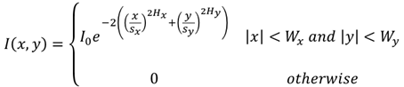
where
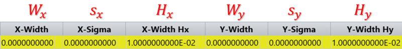
- sx is measured in lens units
- Hx is the "supergaussian" factor for the X direction, with similar definitions for the Y subscripted values. Note if Hx is 1.0, then a typical Gaussian distribution results.Both Hx and Hy must be ≥ 0.01.
The spatial distribution terms are all ignored if the astigmatism term is not zero.
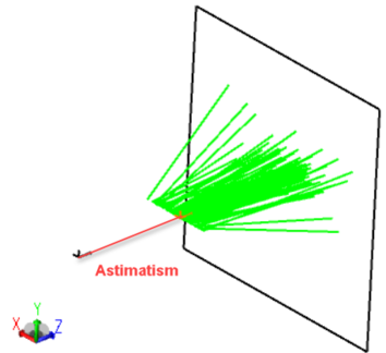
- Astigmatism
If an astigmatism term is defined, the spatial distribution terms are all ignored. This value must be positive, and represents the distance along the local Z axis from which the XZ distribution is measured. At the local XY plane at Z = 0, the resulting ray pattern is a line oriented along the local X axis.
Number of Diodes in X/Y - Spacing of diodes in X/Y in lens units.
If more than 1 diode is desired, the number x, number y, delta x, and delta y spacings may be defined. The diodes will be symmetrically placed in the x and y directions about the local coordinate origin.
The parameters used to define this source are:
| Parameter # | Definition |
| 1-5 | See "Parameters common to all source objects" . |
| 6 | Astigmatism: The distance to offset the XZ distribution in lens units. |
| 7 | X divergence in degrees ( αx ). |
| 8 | X supergaussian factor ( Gx ). |
| 9 | Y divergence in degrees ( αy ). |
| 10 | Y supergaussian factor ( Gy ). |
| 11-12 | Number of diodes in X/Y. |
| 13-14 | Spacing of diodes in X/Y in lens units. |
| 15 | The X half width of the rectangular region from which the rays emanate in lens units ( Wx ). |
| 16 | The Gaussian width of the spatial distribution in the X direction ( sx ). |
| 17 | The X direction spatial distribution super Gaussian factor ( Hx ). |
| 18 | The Y half width of the rectangular region from which the rays emanate in lens units ( Wy ). |
| 19 | The Gaussian width of the spatial distribution in the Y direction ( sy ). |
| 20 | The Y direction spatial distribution super Gaussian factor ( Hy ). |
Use with LightningTrace
The angular distribution of the source is calculated using the X and Y divergence angles for the source (parameters 7, 9) and the X and Y super Gaussian factors (parameters 8, 20). The size and spatial distribution of the source is neglected. As such, the following input parameters have no impact on the LightningTrace results: astigmatism (parameter 6); X and Y half widths for the source (parameters 15, 18); X and Y Gaussian widths for the spatial distribution (parameters 16, 19); X and Y spatial distribution super Gaussian factors (parameters 17, 20). In addition, the array parameters for this source (parameters 11-14) are not accounted for by LightningTrace; regardless of the array parameter values, the source defaults to a single diode (unless otherwise defined under the Sources tab). If an array of diodes must be modeled, the array should be defined via the Array Type option under the Sources tab of the Object Properties dialog box.
Next: