


Source DLL
Although many types of built-in sources are included with OpticStudio, there are times when the best way to model a source is to define an algorithm to generate rays with the desired properties.
OpticStudio also supports user-defined sources as tables of rays; see the Source File discussion .
To define a source using a program, the algorithm which generates random rays must be written and compiled into a Windows Dynamic Link Library, or DLL. Numerous DLLs are provided with OpticStudio with source code. New DLLs may be easily created with a suitable compiler. See also "Comments about DLLs" .
Source DLL parameters
Each DLL may use between zero and 30 user defined data values as parameters in the computation of the source properties. These values are defined by the DLL and are only used by the DLL.
Creating a new Source DLL
The DLL must include two functions: UserSourceDefinition UserParamNames
When launching a ray from a source modeled by a DLL, OpticStudio passes to the UserSourceDefinition function the source parameters, the wavelength, and other data. The UserSourceDefinition function then is required to compute the following values:
x, y, z: the starting coordinates for the ray
l, m, n: the starting direction cosines for the ray
i: the initial relative intensity of the ray (see "Comments on Source DLL relative intensity" below)
These values are returned to OpticStudio and are used to initiate the ray trace. The function UserParamNames is used to define the names of all used parameters. These names appear in the parameter columns of the source DLL object in the NSC Editor.
To check the input and output data for each DLL, check: Data[] values for Source DLLs.
The best way to learn the use of Source DLLs is to study an existing DLL and modify it as needed. The sample DLLs provided with OpticStudio include extensive documentation and comments on the data format; see any of the sample source code files for examples.
All Source DLLs must be placed in the <data>\DLL\Sources folder.
Comments on Source DLL relative intensity
When OpticStudio traces a ray generated by a DLL, the initial power of the ray is given by the source total power, divided by the number of analysis rays, scaled by the relative weight. For this reason, the relative intensity of the ray as computed by the DLL must be set so that the average of all the relative intensities of all the analysis rays requested is 1.0. Note the number of analysis rays is passed as a parameter to the DLL. This condition is required because OpticStudio cannot normalize the entire collection of analysis rays to be traced without generating all the rays before tracing any.
The preferred way to normalize the rays is for the DLL to set the relative intensity of all rays to 1.0, and then choose rays according to the desired probability distribution of the source. This method implies that more rays will be selected with positions and direction cosines that correspond to more energy. The method for doing this is straightforward, and involves integrating the source over all spatial and direction space and using the normalized integral and a uniform random number generator to determine rays. The provided sample FIBER1 DLL illustrates the method.
An alternate way is to use non unity ray weights. This method requires that the DLL compute all the desired rays first, then internally normalize the rays to yield an average weight of 1.0. This method is conceptually simpler but is usually less efficient.
Use with LightningTrace
This source type is not supported by LightningTrace.
Sample Source DLLs
The following sample source DLLs and source code are included with OpticStudio
The DLL and source code (if provided) are in the <Zemax\DLL\Sources> folder.
| CONE.DLL | |
| Description | User-defined parameters |
|
This DLL is similar to the Lambertian_Overfill DLL with two major differences: 1) both uniform and cosine (Lambertian) angular distributions are properly taken into account for all regions in both the source & angular distribution and 2) the user can specify a region of interest based on inner & outer cone angles and start & stop clock angles. When specifying a region of interest, the DLL will scale the intensity of the rays launched into the region while preserving the spatial and angular distribution as if a full 2pi hemi-sphere of rays was launched. This allows a user to efficiently trace either a uniform or Lambertian distribution of rays to small regions far off the source's normal axis. There are 2 distributions to choose from (controlled by the Distribution column):
The cone angle parameters should be between 0° and 90° while the clock angle parameters should be between 0° and 360° degrees; an Outer Cone Angle of 90° and Clock End Angle of 360° represents a 2pi hemi-sphere. Clock angles start on the +x axis and rotate counter clockwise for observers looking backwards towards the source. |
|
|
FIBER1.DLL |
|
| Description | User-defined parameters |
|
A planar fiber model. The rays emanate from a disk of radius R. The intensity profile is given by I(r) = A + Br2 + C r4 , where 0.0 <= r <= R . Once the ray starting position is determined, the ray emanates from the surface into a cone whose numerical aperture depends upon the radial coordinate: NA(r) = D + Er2 + Fr4 Within the angular cone defined by the numerical aperture, the ray distribution is uniform. |
|
|
GaussianSource.dll |
|
| Description | User-defined parameters |
|
This DLL simulates a Gaussian beam. It defines the spatial and angular distribution of the rays using the beam waist, the beam position and the M^2 factor. The real waist is defined as 
The divergence is equal to 
The spatial distribution of the source intensity is given by: 
The angular distribution of the source intensity is given by: 
This DLL doesn't take into account the index of refraction of the source's medium. The latest version of this DLL can be found in the Community: DLL (Source): Non-sequential Astigmatic Gaussian (you must be logged in on an account associated with a supported license to view this page). |
|
|
LAMBERTIAN_OVERFILL.DLL |
|
| Description | User-defined parameters |
|
This DLL allows the user to launch a Lambertian distribution of rays towards – and overfill – a virtual circular aperture. Rays originate from a uniform spatial distribution within the elliptical or rectangular source area. A circular right cone is fit around the virtual target aperture, with the apex at some location within the source area. The ray direction is chosen from a uniform angular distribution within the cone, with an intensity proportional to the solid angle of the cone. The circular cone is slightly larger than the elliptical cross-section of the target aperture, and so the ray may end up slightly outside the target aperture. Thus the target aperture will end up being overfilled, generally by a modest amount. The statistics may be slightly skewed when using a Lambertian intensity distribution. This is because the probability for a given cone angle is dependent on the angle off the local Z-axis, so re-aiming the ray to use a different nominal pointing vector causes a slight decrease in accuracy. As either the source approaches zero spatial size or the target distance increases to infinity, the Lambertian intensity distribution converges to the correct solution. Users should avoid using a large source and a close target distance with a Lambertian distribution. For more accurate statistics when using Lambertian intensity use the Cone.dll. |
|
|
SkewRaysCircular.dll |
|
| Description | User-defined parameters |
|
This DLL sends skew rays to model Gaussian Beam Propagation in non-sequential mode. Skew rays are an efficient and accurate representation of Gaussian beams and can be used to quickly optimize for best focus or to minimize aberrations. It is the non-sequential equivalent of Paul Colbourne's user defined surfaces: Using skew rays to model Gaussian beams. The Source DLL will represent an ideal Gaussian Beam. As shown in the schematic below, at a given wavelength, the Gaussian beam can be described using any set of these parameters:
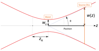 All these parameters are linked by equations:
Note that the wavelength is not scaled by the index of the starting medium in that DLL. |
Definition?: can be 1, 2 or 3. Depending on the flag value 1, 2 or 3, it would use one of the definitions below. If Definition? is not 1, 2 or 3, it will be set to 1. If Definition? = 1
If Definition? = 2
If Definition? = 3
|


Next: