


Lightning Trace


This feature is only available in the Premium and Enterprise editions of Ansys Zemax OpticStudio.
The LightningTrace Control is used to launch and trace a specific set of rays from a discrete mesh for analysis using defined sources, objects, and detectors. The controls on the dialog box are described below.
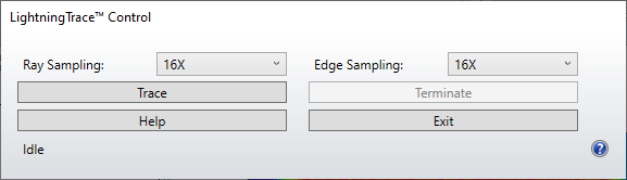
Ray Sampling Sampling used to define the initial mesh for ray launch.
Edge Sampling Sampling used to define the accuracy with which the mesh resolves the edges of objects.
Trace Begins tracing mesh rays from all defined sources.All detectors are automatically cleared (i.e. all pixels on all detectors are reset to have zero energy) prior to raytracing.
Discussion
This feature uses an advanced ray interpolation technology (patent pending) to quickly estimate illumination patterns without the need for tracing millions of rays. The intended application is very fast determination of approximate lighting patterns, allowing initial setup and design of illumination systems to proceed much faster than by using conventional ray tracing (see "The Ray Trace Control" ).
When using LightningTrace, a specific set of rays are launched and traced from each defined source. The launch directions are chosen along a mesh which encapsulates the source. The resolution of this mesh is defined by the Ray Sampling input, and varies from "Low (1X)" to "1024X" (note that as the mesh size doubles, the number of mesh rays quadruples). All rays launched from each mesh start at the same position, corresponding to the center position of the corresponding source. Thus, LightningTrace neglects the size and spatial distribution of each source, and represents each source by its far-field description.
As rays are traced through the system, OpticStudio automatically refines the mesh as needed to ensure that a sufficient number of rays pass through each object on the way from the source to any detectors. The user may control the level of refinement made at the edges of objects via the Edge Sampling input. This input also varies from "Low (1X)" to "1024X".
Rays which leave the mesh are traced in the usual fashion. Mesh rays may only follow the specular ray path, however; splitting and scattering of these rays is not supported. Polarization effects are also not accounted for in tracing the mesh rays. Finally, while the overall color (i.e. Tristimulus values) of each source will be retained during ray tracing, including the variation of color with far-field angle, the spectral distribution of each source is neglected, and an average wavelength for the source is used to trace the mesh rays.
The initial mesh of rays used by the LightningTrace analysis (i.e. the mesh that is generated prior to any automatic refinements made by OpticStudio) may be visualized in the NSC 3D Layout and the NSC Shaded Model (see "NSC 3D Layout" and "NSC Shaded Model" ). Note that the intensity of each ray leaving the mesh is not constant; ray intensities in any angular region are given by the far-field intensity of the source in that region.
Results of the LightningTrace analysis may be observed on Detector Rectangle, Detector Color, and Detector Polar objects (see the "NSC Detectors" chapter). To observe the results on any of these detectors, the detector must either be a terminal detector in the system (i.e. rays do not interact with any other objects after hitting the detector) or the material for the detector must be set to "ABSORB". In addition, only the spatial data will be available when viewing the results on a Detector Rectangle or Detector Color object, while angular data can be obtained by using a Detector Polar object. The results can be viewed on the Detector Viewer (see "The Detector Viewer" ) in the usual fashion.
Nearly all sources are supported by LightningTrace. However, sources defined via the Source DLL, Source Imported, and Source Object objects are also not supported by LightningTrace. For such sources, it is very likely that the size and spatial distribution of the source will be important to the system design. Thus LightningTrace will be inappropriate for modeling a system containing such sources. If a system contains any of the sources not supported by LightningTrace, that system cannot be analyzed with LightningTrace.
Suggestions for use
The main benefit of LightningTrace is speed. Since rays are only traced from a mesh, the number of rays traced through the system will generally be much smaller than used during conventional ray tracing. The response of the system for regions between the mesh are computed using an advanced ray interpolation technology to estimate the behavior of the mesh rays. As such, LightningTrace represents an approximation of the system performance, and in some cases could lead to artifacts (such as hot spots) in the results. A common example of hot spot generation occurs when LightningTrace is used in symmetric (e.g. on-axis) optical systems with results being viewed on detectors with odd numbers of pixels. However, for many lighting and illumination systems the approximations used by LightningTrace are valid. In such systems, ray tracing and optimization (which is available via the NSLT operand; see "Optimization operands" ) can be orders of magnitude faster when using LightningTrace as compared to conventional ray tracing.
Systems for which LightningTrace will work well are those systems in which the size and spatial distribution of all sources is not important to the system design, either because the sources themselves are sufficiently small and/or are sufficiently far enough away from all secondary optics. For example, LightningTrace would be well- suited for modeling systems containing very small LED sources with complex far-field distribution patterns. Thus, LightningTrace can be an ideal tool for designing LED lighting systems, examples of which include architectural lighting or street/roadway lighting (for a description of tools to aid in designing roadway lighting, see "Roadway Lighting" ).
LightningTrace is not the appropriate tool to use for critical illumination systems (in which sources are to be imaged onto detectors) or systems in which the size and spatial distribution of any source is important (such as an LED collimator or beam expander). In addition, LightningTrace will not be accurate for systems containing diffusers (or other scattering components) or for systems with significant dispersion (e.g. due to the presence of diffraction gratings). Finally, LightningTrace cannot be used to model perfectly collimated beams in an optical system. All of the above systems should be designed using conventional ray tracing.
For the class of systems for which LightningTrace is appropriate (e.g. LED lighting), LightningTrace provides users with a fast, virtual prototyping tool for their designs. For these systems, LightningTrace may be used very effectively with the Visual Optimizer (see "Visual Optimization" ) to observe the variation of system performance with design inputs in real time. A conventional ray-trace analysis should always be performed as the design matures to validate the LightningTrace analysis.
Next: