


Ray Trace

The Ray Trace Control is used to launch and trace rays for analysis using defined sources, objects, and detectors. The controls on the dialog box are described below.
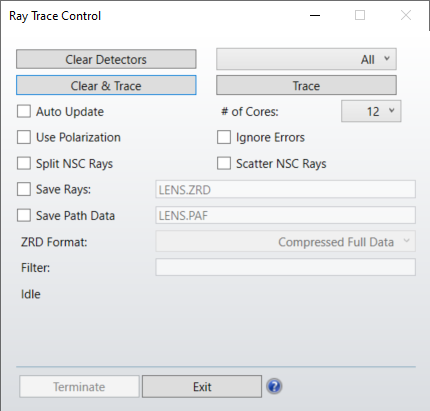
Clear Detectors Select either "All" or any one specific detector to clear. This resets all of the detector's pixels to zero energy.
Clear & Trace Clears the detectors selected and begins tracing rays. See the Clear Detector and Trace settings for details.
Trace Begins tracing rays from all defined sources. Once the trace begins, only the Terminate and Auto Update controls are available. See the discussion below on other effects of initiating a ray trace.
Auto Update If checked, all detectors will be redrawn periodically so progress may be monitored.
# CPU's Selects the number of CPU's over which to spread the ray tracing task. More than 1 may be selected, even on a single CPU computer, in which case the single CPU will time share the multiple simultaneous tasks. The default is the number of processors detected by the operating system. Using more CPU's may speed the computation but requires significantly more memory. If OpticStudio reports insufficient memory errors or begins using the hard disk as a memory cache, try reducing the number of CPU's.
Use Polarization If checked, polarization will be used to determine ray energy, reflection, transmission, absorption, and thin film or coating effects. If Split Rays is checked, Use Polarization will be checked automatically, as it is required for accurate ray splitting.
For more information on how OpticStudio uses polarization, please see Polarization (system explorer) in the System Explorer.
Split NSC Rays If checked, rays will split according to the interface properties as described in "Ray splitting".
Scatter NSC Rays If checked, rays will scatter according to the scatter properties of the interface.
Ignore Errors If checked, errors generated by ray tracing are ignored, and any errors that occur will not terminate the ray trace. This should be turned on with caution, since errors may indicate a serious flaw in the system being traced. However, some perfectly good systems occasionally have a few rays fail because of finite computer precision or other minor problems. If the "lost energy (errors)" given at the end of the ray trace is small relative to the total power of all sources defined, then the few rays which trigger errors can be safely ignored. See "Lost energy".
Save Rays If checked, ray data will be saved to the file name specified. The file name only should be provided with the proper extension (ZRD, DAT, SDF or TM25RAY) and no folder name. See also "Filter" and "Saving ray data to a file" below.
Save Path Data If checked, ray data will be saved as a PAF file to the file name specified. A PAF file contains the same information, and the path data is saved and loaded more quickly from a PAF file from a ZRD. Currently, a PAF file can be used in the Path Analysis tool. The PAF generated ignores the Filter option during the ray trace.
Filter This option is only available if "Save Rays" is checked on. If the filter is not left blank, then the defined filter will be applied to each ray tree traced before it is saved to a file. Only if the ray tree passes the filter will the ray tree be saved. This may substantially reduce the amount of data saved, and therefore may reduce the resulting file size. For a description of the filter syntax, see The Filter String.
Discussion
There are some important considerations to understand when performing a Monte Carlo ray trace. When the detectors are cleared, all the energy counts in each pixel are reset to zero. Once the Trace button is selected, OpticStudio will trace exactly the number of specified analysis rays for each source listed in the NSC Editor. Each source has an associated power in watts or other units ("Analysis Units" ). The initial intensity of each ray from a given source is the total power divided by the number of rays to be traced. For example, for a 1 watt source tracing 1,000,000 rays; each ray initially has 1.0E-06 watts of power associated with it.
If the ray tracing is terminated before all the rays are traced; the total power and peak power as listed on the detector objects will be inaccurate; although the ray distribution will be accurate for the number of rays traced. The analysis cannot be paused and resumed; so once a ray trace is terminated, selecting Trace again will start a new trace.
If the detectors are cleared, then Trace is pressed, the ray trace completes, and Trace is pressed again; all detectors will show the total power from both traces. OpticStudio has no reliable way of knowing how many times rays have been traced between detector clearings; since sources may be added, deleted, or modified at any time.
For accurate power computations, the detectors should be cleared before tracing; then a single trace should be performed without early termination.
Saving ray data to a file
If the Save Rays option is checked, some or all of the traced ray data may be saved to a file. The nature of the data saved depends upon the file name provided.
If the file extension is ZRD, the complete (optionally filtered) ray data will be saved. The folder the file will be placed in is the same as the lens file being traced. The ZRD format is used by OpticStudio in the ray data base viewer (see "The Ray Database Viewer" ). For details on the ZRD format, see "Ray database (ZRD) files".
If the extension is DAT, SDF or TM25RAY, then only rays (optionally filtered) that strike a particular object are saved to a source file. This format is used by Source File objects (see "Source File" ).
To use the source file format, the file name must be of the form n-filename.DAT or n-filename.SDF where n is an integer corresponding to the object number desired. In this case, the filename.DAT or filename.SDF or filename.TM25RAY (with the n- part removed) will be created listing rays that hit object n.
For example, the file name "11-ReferenceObject.DAT" will save all rays that hit object 11 into the file "ReferenceObject.DAT". The file will be placed in the folder <objects>\Sources\Source Files (see "Folders" ). If the file extension DAT is used, the ray data is stored in the older "flux only" format and the wavelength data is lost.
This results in smaller files and is recommended for monochromatic sources only. If the file extension SDF is used, the ray data is stored in the newer "spectral color" format, and wavelength data is stored with every ray. For more information on source file formats see "Binary Source File format".
Saving rays slows down the calculation significantly, as writing data to a file is much slower than the ray tracing. For this reason the Save Rays feature should only be used when the data is needed for subsequent analysis.
If the Save Path Data option is checked, the path data will be saved to a PAF file. This file type does not support additional functionality, and only saves the subset of data to extract path information such as number of rays per path (branches), order of objects the rays hit and the path flux.
Lost energy
When tracing some NSC systems, not every ray can be traced successfully. When a ray trace is terminated, the energy associated with the ray is called "lost energy". The lost energy is measured in source units (see "Source Units" ).There are different causes for terminating the trace of a particular ray:
- If a ray falls below the minimum energy threshold for tracing, the ray will be terminated.
The minimum relative and absolute energy thresholds are described in " Non-sequential (system explorer) " .
The ray trace control reports this type of lost energy as the energy lost due to threshold settings.
- Sometimes geometry errors or round-off errors lead to conditions where the ray can no longer be traced. Geometry errors are usually caused by poorly formed solids or improper nesting of objects. For some rays, correct intercept or refraction data cannot be computed. This may happen when iteration to a surface fails, or the coating data cannot be computed. Rays that hit the maximum number of object intercepts, nesting levels, or segment levels, are also terminated with an error condition. The ray trace control reports these types of lost energy as the energy lost due to errors.
- Rays that strike the edge of an object may be terminated if the local refraction and/or reflection cannot be computed accurately. A ray is considered to strike the edge of an object if the intercept point lies within a threshold distance to the edge, or if two or more objects are struck at the same point and the objects have non-parallel normals at the intercept point. For most objects, the threshold distance is approximately the glue distance in lens units. Along the edge of a faceted object, the threshold distance is approximately the glue distance (interpreted here as a dimensionless number) multiplied by the dimensions of the facet. Note that rays that strike very close to the edge of a part have no useful physical interpretation anyway; an actual object would diffract (or scatter) all energy incident within a few wavelengths of the edge. Rays that miss all objects, or are absorbed by either coatings, bulk transmission, or detectors, are also terminated. OpticStudio absorbs all these rays without error or report, as the energy is not considered lost because the energy is known to be absorbed or propagated out of the system and is thus accounted for.
If the fraction of lost energy is relatively small, lost energy can be ignored. Even well designed and accurate optical models will occasionally have spurious ray errors. Rays that strike within edges or seams between parts and are thus absorbed will usually represent an insignificant fraction of the total energy in the system. If the lost energy is unacceptably high, then the settings (see for example "Minimum Relative Ray Intensity" ) or the object geometry needs to be checked. For assistance in studying geometry errors, see "Create Source Ray From Last Geometry Error Tool"
Next: