


Hologram Lens
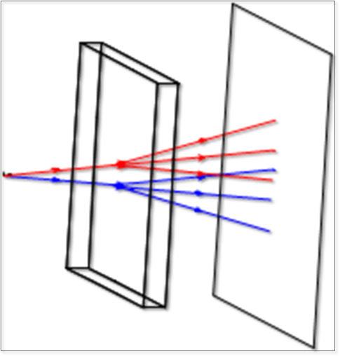
This object is an ideal optically fabricated hologram similar to the Hologram 1 and Hologram 2 sequential surfaces. The hologram is a solid, and may be circular or rectangular in shape. The front and back faces may be plane, spheres, or conic aspheres. The hologram surface is on the front face. See also, Hologram Surface.
This object can also be used as a volume hologram by setting the Volume Hologram? parameter to 1. This does not affect the deviation of rays but it is used in the calculation of efficiency. Similarly, the Hologram Thickness parameter of the object does not effect the geometric shape of the object, only the efficiency.
The diffraction order can only be 0 or 1. If the object has material MIRROR then transmitted rays are terminated. If the object is set as a volume hologram, the Diffraction tab in Object Properties is not available.
For the efficiency of the volume hologram to be calculated, Use Polarization must be selected in the Ray Trace Control. If Split NSC Rays is selected, the Diff Order parameter is ignored and efficiency is calculated from both the 0 and 1st order.
The Hologram object is defined using the following parameters (Parameters 20-27 are only available when Parameter 19 = 1):
| Parameter # | Description | Face Name | Face # |
| 1 | Radial height of the lens object in lens units. This value is used for the y direction half height if the lens is rectangular. | NA | NA |
| 2 | X Half-Width of the lens object in lens units. If zero, the lens is circular; otherwise, the lens is rectangular. | NA | NA |
| 3 | Center thickness of the lens in lens units. | Side | 0 |
| 4-5 | Unused. | NA | NA |
| 6 | Radius 1: The radius of the front face. | Front | 1 |
| 7 | Conic 1: The conic constant of the front face. | Front | 1 |
| 8 | Radius 2: The radius of the back face. | Back | 2 |
| 9 | Conic 2: The conic constant of the back face. | Back | 2 |
| 10 | Holo Type: 1 if both sources converging/diverging, 2 if one source is converging and one is diverging. For more information, see Hologram 1 and Hologram 2. | Front | 1 |
| 11 | Diffraction Order: Multiple orders may be specified in Object Properties Diffraction tab, see Diffraction from NSC Objects. | Front | 1 |
| 12 | Construction Wavelength: The wavelength in micrometers used to fabricate the hologram. | Front | 1 |
| 13-18 | The X, Y, and Z coordinates in lens units of the construction points relative to the vertex of the front face of the hologram. | Front | 1 |
| 19 | Volume Hologram?: 0 for false, 1 for true. | Front | 1 |
| 20 | Hologram Thickness: only used for efficiency calculations, not ray-tracing. | Front | 1 |
| 21 | Refractive index seen by construction beam 1 outside hologram, n1. | Front | 1 |
| 22 | Refractive index seen by construction beam 2 outside hologram, n2. | Front | 1 |
| 23 | Average refractive index of the hologram emulsion, n. | Front | 1 |
| 24 | Modulation of the refractive index, dn. | Front | 1 |
| 25 | Shrinkage: 0 for no shrinkage, else scale of thickness e.g. 0.98 is 2% shrinkage. | Front | 1 |
| 26 | Index Shift: change of average refractive index after developing. | Front | 1 |
| 27 | Consider Fresnel?: 0 for false, 1 for true. | Front | 1 |
Because the object is a closed volume, it may be air, reflective, refractive, or absorbing. If the order is zero or if the ray totally internally reflects at the hologram boundary, no hologram diffraction is computed.
For important information on diffractive objects, see Diffraction from NSC objects .
The reference coordinate is the center of the front face. Face Numbers: Front face Face 1, back face Face 2, all other faces Face 0.
Next: